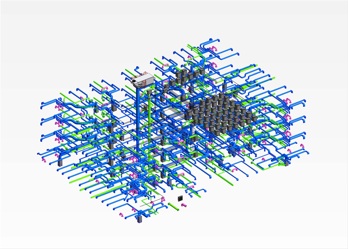
What is HVAC BIM?
HVAC BIM stands for Heating, Ventilation, and Air Conditioning Building Information Modeling. It’s the process of creating intelligent, data-rich 3D models of mechanical systems in a building. Rather than working with traditional 2D drawings, HVAC BIM uses intelligent, data-rich 3D models to accurately represent HVAC components like ducts, piping, air handling units (AHUs), fans, diffusers, VAV boxes, and more.
Unlike traditional 2D CAD, HVAC BIM allows spatial coordination, automated clash detection, and system simulation, enabling engineers and contractors to make informed decisions long before construction begins.
Core Features of HVAC BIM Services
3D HVAC Modeling
This forms the backbone of BIM-based mechanical design. Engineers create 3D digital models of HVAC components, showing how ducts, pipes, and equipment run through a building.
It’s the process of creating a three-dimensional digital representation of all HVAC (heating, ventilation, and air conditioning) components within a building. Unlike traditional 2D drawing, it’s a backbone of BIM-based mechanical design that shows how ducts, pipes, and equipment run through a building.
For example, a 3D model of a hospital’s HVAC system would show how supply and return air ducts circulate through patient rooms, surgical suites, and isolation areas—while respecting infection control protocols.
Parametric Component Modeling
It’s a process of creating intelligent, flexible components in a Building Information Model (BIM) that can automatically adjust their properties based on design requirements. HVAC components (like dampers, valves, and coils) are developed as parametric families in BIM software (like Revit), which means each parametric component contains embedded rules and parameters such as size, material, airflow, pressure, and energy ratings. Their dimensions and properties adapt dynamically if the design is modified at any stage of the design.
Clash Detection and Resolution
One of BIM’s greatest strengths is interdisciplinary coordination. In a complex building project, HVAC systems often intersect with structural beams, electrical conduits, and plumbing pipes. BIM software modeled this system in a shared 3D environment, which helps in detecting overlaps or interferences known as “clashes.” BIM, automatic clash detection tools identify physical conflicts in real-time. Once a clash is detected, teams can then resolve them virtually in the digital model, saving time, money, and effort on-site.
Example: If a duct collides with a structural beam, the software flags it, allowing the mechanical designer to reroute it or adjust beam depth early in the design process.
MEP Coordination
Building information modeling integrates mechanical (HVAC), electrical, and plumbing systems within a building project. The critical systems is designed and installed without interfering with each other or the architectural and structural elements of the building.
Example: In a high-rise office tower, BIM ensures HVAC shafts don’t interfere with plumbing stacks or fire sprinkler lines, maintaining both performance and compliance.
Shop and Fabrication Drawings
Shop and fabrication drawings are generated after the design and coordination stages using Building Information Modeling (BIM). Directly extracted from the 3D model, these drawings are essential for fabricators and site engineers and help minimize interpretation errors. Unlike design drawings, shop and fabrication drawings specify exact dimensions, material specifications, joint details, hanger locations, and clearances, making them essential for accurate and efficient off-site prefabrication and on-site installation of HVAC components.
Builders Work Drawings
Builders Work Drawings (often abbreviated as BW drawings) are specialized construction documents that indicate to the civil or structural contractor what needs to be prepared—like openings, holes, trenches, recesses, sleeves, and supports. The provisions accommodate Mechanical, Electrical, and Plumbing (MEP) services within a building.
Quantity Takeoffs and Bill of Materials (BOM)
Quantity Takeoffs and the resulting bill of materials (BOM) are essential components of the construction planning process. In HVAC BIM services, these functions are automatically extracted from the intelligent 3D model, ensuring precision, consistency, and efficiency in material estimation and procurement.


