
BIM for Steel Detailing: Complete Guide
Introduction
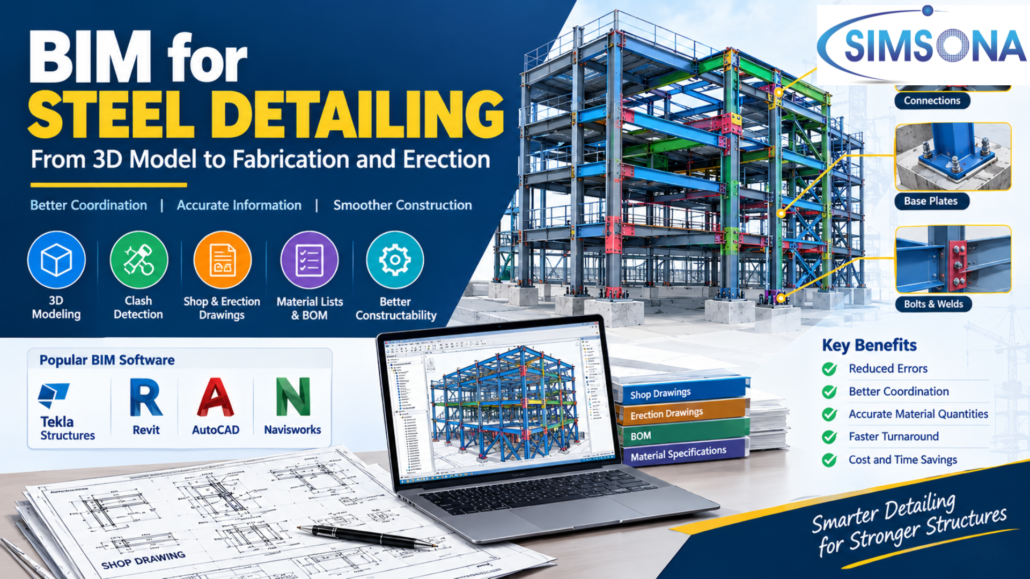
Building Information Modeling has changed the way structural steel projects are designed, detailed, fabricated, and erected. Instead of relying only on conventional two-dimensional drawings, BIM for steel detailing creates a detailed three dimensional digital representation of the steel structure.
A BIM based steel detailing model contains much more than the visual shape of beams and columns. It can include member sizes, material information, connections, bolts, welds, plates, holes, piece marks, elevations, and other information required for fabrication and construction.
For steel fabricators, contractors, structural engineers, and detailers, BIM can provide a more coordinated workflow from structural design through fabrication and erection.
What Is BIM for Steel Detailing?
BIM for steel detailing is the process of creating a detailed three dimensional model of a structural steel system using BIM software.
The model represents the actual physical arrangement of the steel members and their connections. Detailers use the model to develop fabrication information, shop drawings, erection drawings, material lists, and other project deliverables.
A typical steel BIM model may include:
Beams.
Columns.
Braces.
Joists.
Trusses.
Base plates.
Connection plates.
Gusset plates.
Stiffeners.
Bolts.
Welds.
Holes.
Splices.
Miscellaneous steel.
The model can also be coordinated with architectural, structural, mechanical, electrical, and plumbing models to identify potential conflicts before construction.
BIM Steel Detailing vs Traditional Steel Detailing
Traditional steel detailing generally relies heavily on two dimensional plans, sections, elevations, and individual connection details.
BIM adds a three dimensional model that connects the different pieces of information.
For example, in a conventional workflow, a detailer may need to examine several drawings to understand how a beam connects to a column.
With a BIM model, the detailer can examine the connection in three dimensions and understand the relationship between the beam, column, plates, bolts, welds, and surrounding components.
This does not mean that two dimensional drawings are no longer required. Fabrication and erection drawings remain important deliverables. BIM provides the underlying coordinated model from which these drawings and other information can be developed.
Why Is BIM Important for Steel Detailing?
Steel structures often contain thousands of individual components. As project complexity increases, manually coordinating all these components becomes more difficult.
BIM helps create a centralized digital representation of the structure.
The main advantages include:
Improved visualization.
Better coordination.
Clash detection.
Accurate fabrication information.
Reduced drawing inconsistencies.
Improved material quantity information.
Better communication between project teams.
Improved constructability review.
More efficient revisions.
Better coordination between steel and MEP systems
The biggest advantage is that potential problems can often be identified digitally before steel reaches the fabrication shop or construction site.
BIM Steel Detailing Workflow
A typical BIM steel detailing workflow moves through several stages, from reviewing the structural design to creating the final fabrication and erection information.
1. Collect and Review Project Documents
The first step is understanding the project requirements.
The steel detailer reviews the structural drawings, architectural drawings, specifications, connection requirements, design criteria, schedules, RFIs, and other relevant information.
The detailer should also confirm that the latest drawing revisions are being used.
This stage is important because an accurate model cannot be produced from outdated or incomplete information.
2. Create the Structural Steel Model
The steel detailer then develops the three dimensional structural steel model.
Primary members such as columns and beams are modeled first, followed by secondary framing and other steel components.
The model should accurately represent:
Member sizes.
Member locations.
Elevations.
Member orientation.
Connections.
Plates.
Stiffeners.
Bolts.
Welds.
Openings.
Splices.
Other required steel components
The level of detail depends on the project requirements and the intended use of the model.
3. Model Steel Connections
Connections are a critical part of steel detailing.
Depending on the project, the model may contain shear connections, moment connections, brace connections, column splices, beam splices, base plates, gusset plates, and other connection types.
The detailer needs to ensure that the connection geometry works with the surrounding steel.
Important considerations include bolt access, weld access, plate clearances, member interference, erection requirements, and fabrication constraints.
Where connection design is provided separately, the approved connection information needs to be accurately incorporated into the model.
4. Add Fabrication Information
A BIM steel model can contain information required to manufacture individual components.
This may include:
Piece marks.
Member sizes.
Plate dimensions.
Material grades.
Bolt information.
Hole information.
Weld information.
Assembly information.
Connection details.
This information forms the basis for generating fabrication documentation.
5. Perform Clash Detection
One of the most valuable applications of BIM in steel detailing is clash detection.
The steel model can be coordinated against architectural and MEP models to identify conflicts.
For example, a large HVAC duct may pass through the space occupied by a steel beam. A cable tray may conflict with bracing. Plumbing may interfere with a structural column or connection.
Finding these issues during coordination is generally preferable to discovering them during installation.
6. Generate Shop Drawings
Once the model has been reviewed and coordinated, shop drawings can be generated.
Shop drawings provide fabricators with the information required to manufacture the steel components.
Depending on the project, drawings may include:
Anchor bolt plans.
Erection plans.
Assembly drawings.
Single part drawings.
Connection details.
General arrangement drawings.
Sections.
Elevations.
Material information.
Dimensions.
Bolt information.
Weld information.
7. Generate Erection Drawings
Erection drawings communicate how the fabricated steel components are positioned within the building.
They typically identify member marks, grid locations, elevations, orientations, and connection information.
Because the erection drawings are derived from the coordinated steel model, they can remain closely connected to the fabrication information.
8. Generate Bills of Materials
The BIM model can also be used to produce material information.
A Bill of Materials may include quantities, member marks, sizes, lengths, material grades, plate dimensions, and weights.
The exact content depends on project and fabricator requirements.
The important principle is that the BOM should correspond with the approved model and fabrication drawings.
BIM Levels of Detail for Steel Detailing
The amount of information contained in a BIM model depends on the required Level of Development, often expressed through LOD.
Different projects may use different LOD requirements, so the detailer should follow the project’s BIM execution requirements rather than assuming that one level applies to every project.
For steel detailing, higher development levels generally involve increasingly specific geometry and information.
LOD 100
LOD 100 represents conceptual information.
The model provides a general representation of the building or structural system rather than detailed fabrication information.
LOD 200
LOD 200 provides approximate geometry and general information about structural elements.
It can be useful during early design stages but is normally insufficient for detailed steel fabrication.
LOD 300
LOD 300 represents accurately defined design geometry.
Steel members have more specific sizes, locations, and relationships.
This level can support detailed design coordination.
LOD 350
LOD 350 adds information about relationships between building components and their interfaces.
For steel structures, this can become particularly useful when coordinating connections and interfaces with other systems.
LOD 400
LOD 400 represents fabrication and assembly level information.
For steel detailing, this can include highly detailed members, connections, plates, bolts, welds, holes, and fabrication information.
This is the level most closely associated with detailed fabrication modeling.
LOD 500
LOD 500 represents an as constructed condition.
The model reflects verified information about the completed installation rather than simply representing design intent.
BIM Software Used for Steel Detailing
Different projects use different software depending on project requirements, fabricator workflows, and coordination standards.
Commonly used platforms include:
Tekla Structures
Tekla Structures is widely used for detailed structural steel modeling, connection modeling, fabrication drawings, and material information.
Revit
Revit can be used for structural modeling and BIM coordination, particularly when structural steel needs to be coordinated with architectural and MEP models.
AutoCAD
AutoCAD continues to be useful for two dimensional drafting, detailing, and documentation.
Navisworks
Navisworks can be used for model coordination, visualization, clash detection, and construction sequencing.
The software selection should ultimately depend on the project’s requirements and the deliverables expected by the client, fabricator, engineer, and contractor.
BIM and Steel Shop Drawings
Steel shop drawings are one of the most important outputs of a BIM based detailing process.
Instead of creating each drawing independently, the detailer can generate drawings from the coordinated model.
When the model is updated correctly, associated drawings and schedules can also be updated as part of the detailing workflow.
A typical steel shop drawing package may include:
General arrangement drawings
Assembly drawings.
Single part drawings.
Connection details.
Anchor bolt plans.
Erection drawings.
Bolt lists.
Weld information.
Piece marks.
This model based approach can help reduce inconsistencies between different documents.
BIM Clash Detection for Steel Structures
Clash detection is particularly important when structural steel shares limited space with building services.
Consider a building containing:
Structural steel beams.
HVAC ducts
Electrical cable trays.
Plumbing pipes.
Fire protection systems.
Ceilings.
Architectural elements.
If these systems are developed independently, physical conflicts can occur.
A coordinated BIM model allows project teams to examine these relationships before construction.
Steel specific clashes can include:
Beam versus duct.
Column versus wall.
Brace versus pipe.
Connection versus MEP equipment.
Beam versus ceiling.
Base plate versus foundation component.
Steel framing versus architectural opening.
Identifying these conflicts early can reduce the need for field modifications.
BIM for Steel Fabrication
The benefits of BIM extend beyond drawing production.
A detailed steel model can become an important source of fabrication information.
Depending on the software and fabrication workflow, model information can support:
CNC data.
Material lists.
Cutting information.
Assembly information.
Bolt lists.
Piece marks.
Fabrication drawings.
Production planning.
The connection between detailing and fabrication can therefore become more integrated.
For fabricators, this can improve traceability because individual components can be tracked from the digital model through fabrication and erection.
BIM for Steel Erection
BIM also supports the erection stage.
The erection team needs to know where each steel component belongs and how the structure fits together.
A coordinated model provides a three dimensional reference for understanding:
Member locations.
Grid positions.
Elevations.
Piece marks.
Connection locations.
Steel sequence.
Potential access problems.
Complex structural areas.
For complicated projects, the model can also support construction sequencing and visualization.
BIM and Quality Control in Steel Detailing
BIM does not automatically guarantee an accurate steel model.
Quality control remains essential.
A BIM based QA/QC process should compare the model against the approved structural design and project requirements.
Typical checks include:
Member sizes.
Member locations.
Elevations.
Connections.
Bolts.
Welds.
Plate dimensions.
Piece marks.
Material grades.
Drawing information.
BOM information.
Clashes.
Clearances.
Revisions.
The final shop drawings should also be checked against the model.
This creates several layers of quality control rather than relying on visual inspection alone.
BIM for Structural Steel Coordination
Structural steel rarely exists independently within a building.
It interacts with architecture, concrete, MEP systems, equipment, cladding, ceilings, stairs, and other construction elements.
BIM provides a common digital environment for coordinating these systems.
For example, a steel beam may need to pass through a particular elevation while an HVAC duct requires the same space.
Rather than waiting until installation, the conflict can be identified during coordination and resolved through the appropriate design or project review process.
Benefits of BIM for Steel Detailers
For steel detailing companies, BIM can improve both technical coordination and project workflow.
Better Visualization
A three dimensional model allows detailers and project teams to understand complex structural arrangements more easily.
Reduced Coordination Problems
Potential conflicts between steel and other disciplines can be identified before fabrication.
More Consistent Documentation
Shop drawings, erection drawings, material lists, and model information can be coordinated through a common model based workflow.
Improved Revision Management
When approved design changes occur, the model provides a central location for updating the affected steel components.
Better Material Information
Detailed model information can support more accurate material schedules and Bills of Materials.
Improved Communication
Engineers, architects, contractors, fabricators, and detailers can discuss the same three dimensional representation of the project.
Challenges of BIM Steel Detailing
Although BIM offers significant advantages, it also requires proper processes and skilled professionals.
Some common challenges include:
High modeling requirements.
Need for experienced detailers.
Complex connection modeling.
Large model sizes.
Software interoperability.
Coordination between different file formats.
Frequent design revisions.
Incomplete design information.
Data management.
Training requirements.
BIM should therefore be treated as a structured project workflow rather than simply a software upgrade.
BIM for Steel Detailing and Constructability
Constructability is another important consideration.
A model may look correct geometrically but still create problems during fabrication or erection.
For example, a connection may technically fit within the model but leave insufficient space for a worker to install a bolt.
Similarly, a weld may be shown correctly but be difficult to access after the member is erected.
Constructability review considers questions such as:
Can the component be fabricated?
Can it be transported?
Can the connection be assembled?
Can bolts be installed?
Can welds be performed?
Is there sufficient access?
Can the member be erected safely?
Are adjacent components creating an obstruction?
BIM makes these relationships easier to visualize and review.
BIM for Complex Steel Structures
BIM becomes particularly valuable for projects with complicated geometry or dense structural framing.
Examples include:
Industrial facilities.
Commercial buildings.
Warehouses.
Manufacturing facilities.
Sports structures.
Large infrastructure projects.
Multi story steel buildings.
Complex roof structures.
Structures with extensive MEP services.
In such projects, the number of members and connections can make conventional coordination increasingly difficult.
A detailed BIM model provides a common digital reference for understanding the complete steel system.
The Future of BIM in Steel Detailing
The role of BIM in steel detailing continues to expand beyond three dimensional modeling.
Modern workflows increasingly connect design, detailing, fabrication, construction, and facility information.
The future direction includes greater integration between:
Structural engineering.
Steel detailing.
Fabrication.
CNC manufacturing.
Construction planning.
Cloud collaboration.
Reality capture.
Digital quality control.
Construction sequencing.
As these workflows become more connected, the steel model can become more than a drawing production tool. It can serve as a digital information source throughout the project lifecycle.
BIM for Steel Detailing: Final Thoughts
BIM for steel detailing provides a structured approach to developing, coordinating, documenting, and managing structural steel information.
Its value comes from connecting the different stages of a project. Structural design information can be developed into a detailed steel model, coordinated with other disciplines, converted into shop and erection drawings, and connected with fabrication and material information.
The most effective BIM steel detailing workflow combines accurate modeling with experienced detailers, proper QA/QC, clash detection, constructability review, and disciplined revision management.
For steel fabricators, contractors, engineers, and construction companies, BIM can provide a more coordinated way to move from structural design to fabrication and erection while reducing avoidable information gaps and coordination problems.
For a BIM and steel detailing service provider such as Simsona, integrating detailed steel modeling with BIM coordination, shop drawing production, material information, and quality control can help support steel projects from design coordination through fabrication and construction.
:::
 301-774-0880