Level of Detail || Level of Development in BIM Modeling || Simsona

level of details and level of development

Building Information Modeling (BIM) has changed the way architects, engineers, contractors, and owners plan, design, construct, and manage buildings. As BIM models become more detailed throughout a project, it becomes important to understand exactly what that increasing detail represents.

Two terms that are often confused are Level of Detail (LOD) and Level of Development (LOD). Although they sound similar and are sometimes used interchangeably, they describe different aspects of a BIM model.

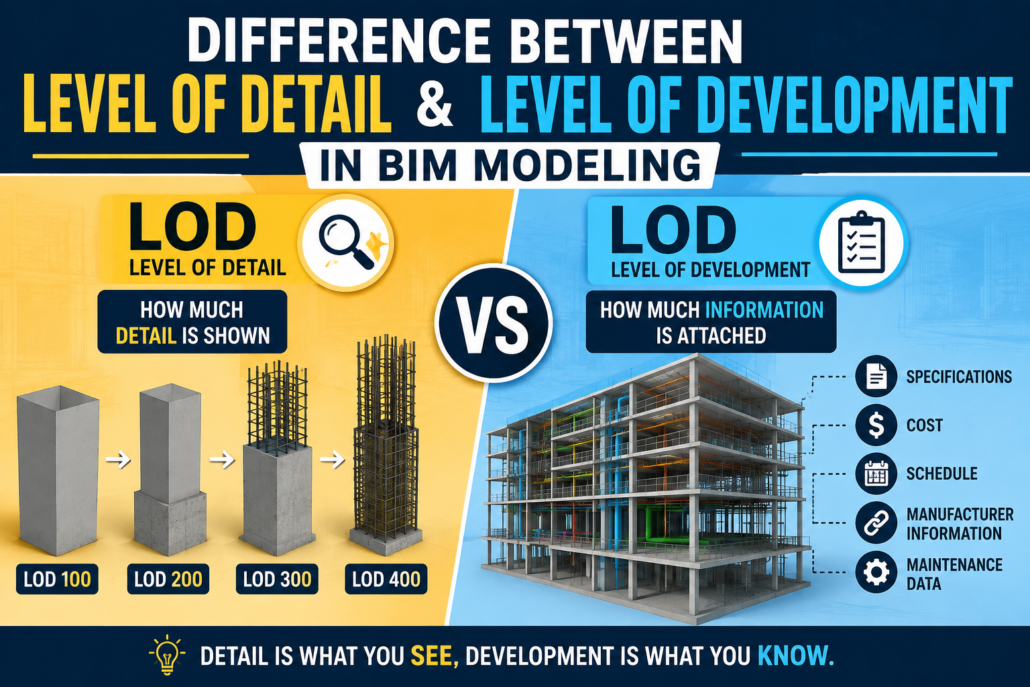
Level of Detail focuses primarily on how much graphical detail is included in a model element, while Level of Development focuses on how reliable, complete, and usable that element’s information and geometry are for a particular project stage.

Understanding this difference helps project teams establish realistic modeling expectations, avoid unnecessary modeling work, and ensure that BIM deliverables are suitable for their intended purpose.

What Is Level of Detail in BIM?

Level of Detail (Level of Detail) describes the amount of graphical or visual detail represented in a BIM model element.

In simple terms, it answers the question:

“How much detail can I see in the model?”

For example, consider a door in a BIM model.

At a low level of detail, the door may simply appear as a basic rectangular opening with a door panel. At a higher level of detail, the same door could include the frame, handles, hinges, glazing, seals, hardware, and other physical features.

Level of Detail is therefore closely associated with the visual representation and geometric complexity of an object.

Example of Level of Detail

Imagine modeling an air-handling unit (AHU).

At a basic level of detail, the AHU may appear as a simple rectangular box showing its approximate size.

At a higher level of detail, the model might show:

  • Access panels.
  • Fans.
  • Coils.
  • Filters.
  • Connections.
  • Control panels.
  • Internal components.
  • Mounting arrangements.

The model becomes increasingly visually detailed, but that does not automatically mean that all of the information has been developed or verified for construction.

This distinction is extremely important.

What Is Level of Development in BIM?

Level of Development (LOD) describes the degree to which a BIM element has been developed, coordinated, verified, and can be relied upon for a specific project use.

It answers a different question:

“How reliable and usable is this model element?”

Level of Development is therefore not simply about how realistic an object looks. It is about the extent to which the geometry and associated information have been developed to support project decisions and workflows.

For example, an architectural wall may be represented with considerable graphical detail but still not be sufficiently developed for fabrication.

Conversely, a relatively simple-looking model element may contain accurate dimensions, specifications, location information, manufacturer data, and other information required for a particular stage of the project.

Why Are Level of Detail and Level of Development Confused?

The confusion largely comes from the fact that both concepts involve the progression of BIM models from simple representations to more developed representations.

The abbreviation LOD has also historically been used for both Level of Detail and Level of Development.

However, they are not the same concept.

A useful way to remember the distinction is:

Level of Detail = How much you can see.

Level of Development = How much you can trust and use.

A highly detailed model does not necessarily represent a highly developed model.

Level of Detail vs Level of Development

The key differences can be summarized as follows:

AspectLevel of DetailLevel of Development
Primary focusGraphical representationModel reliability and usability
Main questionHow much detail is shown?How developed is the element?
Concerned withGeometry and appearanceGeometry, information, coordination, and reliability
Typical purposeVisualization and presentationDesign, coordination, construction, fabrication, or asset management
Information reliabilityNot necessarily impliedImportant consideration
Construction suitabilityCannot be assumedCan be defined for specific uses
ExampleDetailed door with handles and hingesDoor accurately developed for coordination or procurement
Project decision supportLimited by itselfDesigned to support defined project decisions

A Simple Example: BIM Door

Consider a door in an architectural BIM model.

Low Level of Detail

The door is represented by a simple rectangular panel.

It communicates:

  • Approximate location
  • Basic size
  • Opening direction

The object is visually simple.

High Level of Detail

The door includes:

  • Door leaf.
  • Frame.
  • Handles.
  • Hinges.
  • Glazing.
  • Door closer.
  • Threshold.
  • Hardware.

Visually, the model is much more detailed.

However, the presence of these components does not automatically mean the door has been fully developed for construction.

Higher Level of Development

A developed door element could include reliable information such as:

  • Verified dimensions.
  • Door type.
  • Material.
  • Fire rating.
  • Acoustic rating.
  • Hardware requirements.
  • Manufacturer information.
  • Installation requirements.
  • Coordination with adjacent elements.

The model may not need every tiny physical component to be useful.

This is the fundamental difference between detail and development.

Level of Detail Is Mainly About Geometry

Level of Detail generally deals with the graphical representation of model elements.

As the Level of Detail increases, objects generally become more visually complex.

For example:

Low detail:

A column may be represented as a simple rectangular or circular volume.

Medium detail:

The column may include its actual dimensions, shape, offsets, and connections.

High detail:

The column may show reinforcement, plates, bolts, welds, connection components, and other physical features.

However, adding all these components does not automatically make the model more useful.

In fact, excessive graphical detail can make a BIM model unnecessarily large and difficult to manage.

Level of Development Is About Purpose and Reliability

Level of Development is closely connected to project requirements and intended use.

A model element should be developed only to the extent necessary to support the required project activity.

For example, during early design, a structural column may only need approximate dimensions and location.

During detailed design, its size, material, structural properties, and relationship with other building elements may need to be established.

During construction, the element may need additional information for coordination, sequencing, procurement, or installation.

The model therefore becomes progressively more useful—not simply more visually complex.

Understanding LOD 100, 200, 300, 350, 400 and 500

In many BIM workflows, Level of Development is described using LOD stages such as LOD 100, 200, 300, 350, 400, and 500.

These levels are commonly used to communicate how developed a model element is at different stages of a project.

LOD 100 – Conceptual Representation

LOD 100 represents conceptual information.

Elements may be shown symbolically or approximately.

Typical uses include:

  • Conceptual design.
  • Early planning.
  • Area studies.
  • Massing.
  • Preliminary cost analysis.

For example, a building may contain conceptual masses representing floors, zones, or major building systems.

The geometry is not intended to represent final construction information.

LOD 200 – Approximate Geometry

At LOD 200, elements are represented with approximate quantities, sizes, shapes, locations, and orientations.

The information is more developed than at LOD 100 but may still contain assumptions.

Typical uses include:

  • Design development.
  • Preliminary analysis.
  • Space planning.
  • Early coordination.
  • Approximate quantity takeoffs.

For example, a mechanical duct may be modeled with an approximate size and route rather than final coordinated dimensions.

LOD 300 – Specific and Accurate Design

LOD 300 represents elements with sufficient geometric and information development to support detailed design documentation.

Elements generally have:

  • Specific size.
  • Specific shape.
  • Specific location.
  • Specific orientation.
  • Appropriate design information.

LOD 300 can support tasks such as:

  • Construction documentation.
  • Detailed design.
  • Quantity estimation.
  • Design coordination.

At this stage, model elements are intended to represent the designed condition rather than simply an approximation.

LOD 350 – Construction Coordination

LOD 350 adds information necessary for coordination between building elements and systems.

This is particularly useful for construction coordination.

For example, an element may include relationships and interfaces with:

  • Structural systems.
  • Architectural elements.
  • Mechanical systems.
  • Electrical systems.
  • Plumbing systems.
  • Other construction components.

LOD 350 is particularly valuable when teams need to understand how different systems physically interact.

LOD 400 – Fabrication and Installation

LOD 400 represents a highly developed model suitable for fabrication, assembly, and installation-related activities.

Depending on the element and project requirements, the model may include:

  • Fabrication-level geometry.
  • Connections.
  • Assembly information.
  • Installation requirements.
  • Manufacturer-specific information.
  • Detailed dimensions.

For example, a structural steel model developed for fabrication may include detailed connections, plates, bolts, weld information, and other fabrication requirements.

LOD 500 – As-Built or Field-Verified Information

LOD 500 is generally associated with an element that represents the installed or existing condition and has been verified in the field.

It is often used for:

  • Facility management
  • Asset management.
  • Operations and maintenance.
  • Existing-condition documentation.

The important point is that LOD 500 is not simply “more detailed than LOD 400.”

Instead, it focuses on the verified status of the element.

A Common Misunderstanding: LOD 500 Does Not Mean Maximum Detail

One of the most common misconceptions in BIM is that LOD 500 means the most detailed possible model.

That is not necessarily true.

LOD 500 primarily relates to field-verified or as-constructed information, not an unlimited increase in graphical complexity.

For example, an installed pump does not need to be modeled down to every internal component simply because the project requires LOD 500.

The model should contain the information required for its intended operational or asset-management purpose.

Can a Model Have High Detail but Low Development?

Yes.

This is one of the most important concepts to understand.

Imagine a BIM family of a highly realistic toilet fixture.

The family contains:

  • Detailed ceramic geometry.
  • Internal components.
  • Small fittings.
  • Decorative features.
  • Realistic materials.

It looks extremely accurate.

However, suppose the model does not contain:

  • Verified dimensions.
  • Correct connection locations.
  • Manufacturer information.
  • Required specifications.
  • Installation information.

The object may have high graphical detail but limited development for construction purposes.

It looks impressive, but it may not be reliable enough to support the intended workflow.

Can a Model Have Lower Detail but Higher Development?

Yes.

Consider a simple equipment box representing a piece of mechanical equipment.

The geometry may be relatively basic, but the model could contain:

  • Correct dimensions.
  • Accurate location.
  • Equipment identification.
  • Manufacturer.
  • Model number.
  • Capacity.
  • Service requirements.
  • Connection information.
  • Maintenance information.

For facility management, this model could be highly useful even though the geometry is not extremely detailed.

This demonstrates why visual complexity should not be confused with information maturity.

Level of Detail and Level of Development in Different Project Stages

The relationship becomes easier to understand when looking at a typical project lifecycle.

Conceptual Design

At the conceptual stage, teams generally need simple representations.

The focus may be on:

  • Building massing.
  • Areas.
  • Volumes.
  • Preliminary systems.
  • General relationships.

High graphical detail is usually unnecessary.

Design Development

As the design progresses, model elements become more specific.

Teams may establish:

  • Dimensions.
  • Materials.
  • Locations.
  • System layouts.
  • Design parameters.

The objective is to make the model useful for design decisions and coordination.

Construction Documentation

The model needs to represent the designed solution with sufficient accuracy to generate drawings, schedules, quantities, and other deliverables.

The emphasis is increasingly on reliable information and coordinated geometry.

Construction and Fabrication

Contractors, fabricators, and specialist subcontractors may require much more developed information.

Depending on project requirements, this can include:

  • Fabrication geometry.
  • Connections.
  • Installation details.
  • Shop drawing information.
  • Sequencing information.
  • Trade-specific requirements.

This is where high Level of Development becomes particularly important.

Operations and Facility Management

Once construction is complete, the model may be updated with verified information about installed assets.

The emphasis shifts toward:

  • Asset identification.
  • Equipment information.
  • Maintenance requirements.
  • Manufacturer information.
  • Location.
  • Operational data.

The model does not necessarily need maximum graphical detail.

Instead, it needs accurate and useful information.

How the Difference Affects BIM Modeling

Understanding the distinction can significantly improve BIM modeling workflows.

Without clear requirements, BIM teams may spend excessive time modeling unnecessary details.

For example, a BIM modeler may create detailed bolts, screws, brackets, and internal components that provide little value to the project’s intended use.

This can result in:

  • Larger model sizes.
  • Slower software performance.
  • More complex coordination.
  • Longer modeling time.
  • Increased chances of errors.
  • Difficult model management.

A well-defined Level of Development helps teams determine what information actually needs to be modeled.

Why Excessive Level of Detail Can Be a Problem

More detail is not always better.

A highly detailed model can create unnecessary computational and coordination requirements.

For example, modeling every screw in a large building can dramatically increase the number of model objects without providing meaningful project value.

Instead, BIM teams should ask:

Does this detail support a project requirement?

If the answer is no, it may not need to be modeled.

This approach is often described as modeling to purpose.

Level of Development and BIM Deliverables

BIM deliverables should clearly define what is expected from each discipline.

A BIM Execution Plan (BEP) can establish requirements such as:

  • Required LOD for different project stages
  • Model element responsibilities.
  • Information requirements.
  • Coordination requirements.
  • Naming conventions.
  • File exchange requirements.
  • Model submission schedules.
  • Approval procedures.

For example, an architectural team may be required to develop doors to a particular level for design coordination, while a specialist contractor may later develop the same doors further for procurement or installation.

This prevents different teams from making different assumptions about what “complete” means.

How LOD Helps BIM Coordination

LOD is particularly important in multidisciplinary BIM coordination.

Architectural, structural, mechanical, electrical, plumbing, and fire protection models often need to work together.

If one discipline models elements with significantly different expectations, coordination can become difficult.

For example, an MEP contractor may require accurately developed ductwork and equipment connections, while an architectural model may only contain simplified representations of certain components.

Clearly defining development requirements helps teams understand:

  • What each model should contain.
  • What information can be relied upon.
  • What has not yet been developed.
  • Which elements require further coordination.

This reduces misunderstandings during coordination meetings and clash detection.

Level of Detail vs Level of Development: Practical Example

Consider a ceiling-mounted air-conditioning unit.

Level of Detail Approach

The modeler focuses on making the equipment visually accurate.

The model might include:

  • Casing.
  • Grilles.
  • Fans.
  • Panels.
  • Filters.
  • Detailed internal components.

The result may look highly realistic.

Level of Development Approach

The modeler focuses on information required for the project’s current purpose.

The model may include:

  • Correct equipment size.
  • Accurate location.
  • Service clearance.
  • Duct connections.
  • Electrical connection.
  • Equipment identification.
  • Manufacturer information.
  • Installation requirements.

The second approach may produce a simpler-looking object but a much more useful BIM element.

The Role of Information in BIM

BIM is not simply 3D modeling.

A BIM model combines geometry with structured information.

That information may include:

  • Dimensions.
  • Materials.
  • Specifications.
  • Classification.
  • Manufacturer data.
  • Product information.
  • Performance data.
  • Installation information.
  • Maintenance requirements.
  • Asset information.

Therefore, evaluating a BIM model solely by its visual appearance can be misleading.

A model that looks highly detailed may still contain incomplete or unreliable information.

Level of Detail and Level of Development Should Work Together

Although the two concepts are different, they are closely related.

As a project progresses, graphical detail may increase alongside the development of information.

However, the two should not automatically increase at the same rate.

For example, a project may require a highly accurate equipment location and connection geometry while using a relatively simplified representation of the equipment itself.

The correct balance depends on the intended use of the model.

Best Practices for Managing Level of Detail and Level of Development

1. Define Requirements Early

Project teams should establish modeling requirements before significant modeling begins.

This prevents teams from making assumptions about what needs to be modeled.

2. Model According to Purpose

Every modeled component should have a reason for being modeled at a particular level.

Ask whether the geometry or information supports:

  • Design.
  • Coordination.
  • Quantity takeoff.
  • Fabrication.
  • Installation.
  • Construction.
  • Facility management.

3. Avoid Unnecessary Geometry

Do not add small components simply because they make a model look realistic.

Unnecessary detail can increase file size and reduce performance.

4. Define Information Requirements

Geometric development is only one part of BIM.

Specify what non-graphical information is required for each element.

5. Use LOD Matrices

A project-specific LOD matrix can define the expected development of different elements at different stages.

For example:

ElementConceptDesignCoordinationConstructionFM
WallsBasicDefinedCoordinatedVerifiedAsset-related data
DoorsApproximateSpecifiedCoordinatedInstalledProduct/maintenance data
DuctworkConceptualSizedCoordinatedFabricatedSystem information
EquipmentApproximateSpecifiedConnectedInstalledAsset information

The exact requirements should always be established according to the project’s BIM standards and contractual requirements.

6. Coordinate Before Adding Detail

It is usually more valuable to establish accurate locations and relationships between systems before spending time on tiny graphical details.

A coordinated model with appropriate detail is generally more useful than a visually impressive but poorly coordinated model.

Common Mistakes to Avoid

Mistake 1: Assuming More Detail Means Higher LOD

A highly detailed object is not automatically highly developed.

Mistake 2: Using LOD as a Generic “Quality Score”

LOD should communicate what an element has been developed to support, not simply whether the model is good or bad.

Mistake 3: Modeling Everything

Not every physical component needs to be represented individually.

Mistake 4: Ignoring Non-Graphical Information

BIM is more than geometry. Information requirements are equally important.

Mistake 5: Treating LOD 500 as Maximum Detail

LOD 500 is associated with verified existing or installed conditions, not necessarily maximum graphical detail.

Level of Detail vs Level of Development: The Easiest Way to Remember

If you want to remember the difference quickly, use this simple comparison:

Level of Detail asks:

“How much can I see?”

Level of Development asks:

“How much has been developed and how reliable is it for the intended use?”

For example, a highly realistic chair may have a high Level of Detail, but if the chair’s manufacturer, specifications, location, and procurement information are missing, it may not be highly developed for a specific project purpose.

On the other hand, a simple equipment box with verified dimensions, manufacturer information, installation data, and asset information can be highly developed even though its graphical representation is relatively simple.

Conclusion

The difference between Level of Detail and Level of Development in BIM modeling is subtle but extremely important.

Level of Detail primarily describes the graphical complexity of a BIM element, while Level of Development describes the degree to which that element has been developed and can be relied upon for a particular project purpose.

A model should therefore not be judged simply by how realistic it looks.

Effective BIM modeling is about providing the right amount of geometry and information at the right stage of the project.

When project teams clearly distinguish between detail and development, they can reduce unnecessary modeling, improve model performance, strengthen coordination, and deliver BIM models that are genuinely useful for design, construction, fabrication, and facility management.

Ultimately, the goal of BIM is not to create the most detailed model possible. The goal is to create a model that contains the right information, at the right time, for the right purpose.

BIM Adoption Challenges for General Contractors and How to Fix Them

BIM Adoption Challenges

Introduction

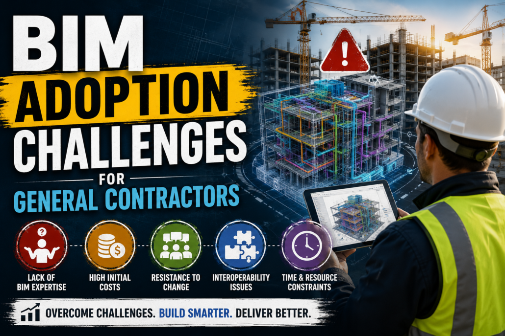
Building Information Modeling (BIM) has transformed the construction industry by improving collaboration, reducing errors, and enabling data-driven project management. While architects and engineers have embraced BIM for design and coordination, many general contractors (GCs) still face significant obstacles when integrating BIM into their day-to-day construction operations.

For general contractors, BIM is no longer just a 3D visualization tool—it has become a comprehensive project management platform that supports scheduling (4D), cost estimation (5D), quantity takeoffs, clash detection, site logistics, safety planning, and facility management. Owners across the United States increasingly require BIM deliverables for public infrastructure, healthcare facilities, educational institutions, airports, and commercial developments.

Despite its proven advantages, successful BIM implementation requires changes in technology, workflows, company culture, and workforce skills. Understanding these challenges—and knowing how to overcome them—is essential for contractors who want to remain competitive.

This article explores the most common BIM adoption challenges for general contractors and practical strategies to solve them.

Why BIM Matters for General Contractors

General contractors coordinate multiple stakeholders, including:

  • Architects
  • Structural engineers
  • MEP consultants
  • Specialty subcontractors
  • Fabricators
  • Suppliers
  • Owners
  • Facility managers

BIM acts as a centralized digital environment where every stakeholder can collaborate using accurate project information.

Benefits include:

  • Reduced RFIs
  • Better clash detection
  • Improved construction sequencing
  • Accurate quantity takeoffs
  • Lower rework costs
  • Better schedule management
  • Enhanced communication
  • Improved safety planning
  • Digital project documentation

According to industry research, projects using mature BIM workflows often experience measurable reductions in coordination errors and construction delays compared with traditional 2D-based workflows.

Major BIM Adoption Challenges for General Contractors

1. High Initial Investment

One of the biggest concerns is the upfront cost.

Implementing BIM typically involves:

  • Software licenses
  • Powerful workstations
  • Cloud collaboration platforms
  • Employee training
  • BIM consultants
  • Process development
  • Hardware upgrades

Small and medium-sized contractors often hesitate because the return on investment isn’t immediately visible.

How to Fix It

Rather than adopting everything at once:

  • Start with pilot projects.
  • Use subscription-based software.
  • Prioritize high-impact workflows.
  • Expand BIM capabilities gradually.
  • Track measurable ROI from completed projects.

2. Resistance to Organizational Change

Many experienced construction professionals have spent decades using traditional workflows.

Common concerns include:

  • “We’ve always done it this way.”
  • Fear of new technology
  • Concerns about job security
  • Lack of confidence using software

Without leadership support, BIM adoption often fails.

How to Fix It

Successful companies:

  • Build executive-level BIM commitment.
  • Communicate benefits clearly.
  • Involve project managers early.
  • Celebrate small BIM successes.
  • Develop BIM champions within each department.

Culture change is often more important than software implementation.

3. Lack of Skilled BIM Professionals

Finding experienced BIM coordinators and model managers remains difficult.

General contractors often struggle to hire professionals with experience in:

  • Model coordination
  • Navisworks clash detection
  • Revit construction workflows
  • Quantity extraction
  • 4D simulation
  • BIM execution planning

How to Fix It

Invest in:

  • Internal training programs
  • Certification courses
  • Mentorship initiatives
  • Partnerships with BIM consultants
  • University recruitment programs

Upskilling existing employees is often more cost-effective than relying solely on new hires.

4. Poor Model Quality from Design Teams

General contractors frequently inherit models that were created primarily for design—not construction.

Problems include:

  • Missing elements
  • Incorrect object data
  • Inconsistent naming
  • Duplicate components
  • Low Levels of Development (LOD)
  • Poor coordination

These issues limit the model’s usefulness during construction.

How to Fix It

Establish clear BIM requirements before construction begins.

Create a comprehensive:

  • BIM Execution Plan (BEP)
  • Model review checklist
  • LOD requirements
  • Naming standards
  • Data validation process

Early model audits can identify issues before they affect field operations.

5. Interoperability Problems

Construction teams often use multiple software platforms, including:

  • Autodesk Revit
  • Navisworks
  • Tekla Structures
  • Civil 3D
  • Archicad
  • Bentley applications
  • Primavera P6
  • Microsoft Project

Data exchange between platforms isn’t always seamless.

How to Fix It

Use open standards whenever possible:

  • IFC
  • BCF
  • COBie

Adopt Open BIM workflows that improve collaboration between different software ecosystems.

6. Unclear BIM Standards

Without company-wide standards, every project team develops different modeling practices.

This leads to:

  • Inconsistent file structures
  • Naming confusion
  • Version control issues
  • Coordination delays

How to Fix It

Develop company BIM standards covering:

  • File naming
  • Model organization
  • Shared coordinates
  • Clash workflows
  • Approval processes
  • Data management
  • Deliverables

Consistency improves efficiency across every project.

7. Difficulty Measuring ROI

Many contractors know BIM is beneficial but struggle to quantify its financial value.

Questions often include:

  • Did BIM actually save money?
  • How much rework was avoided?
  • Were schedules shortened?
  • Were RFIs reduced?

Without metrics, future investment becomes difficult to justify.

How to Fix It

Track KPIs such as:

  • Number of clashes resolved before construction
  • RFI reduction
  • Change order reduction
  • Schedule savings
  • Rework costs
  • Labor productivity
  • Material waste reduction

Data-driven reporting demonstrates BIM’s business value.

8. Subcontractor BIM Readiness

Not all subcontractors possess BIM expertise.

Common issues include:

  • Limited software access
  • No BIM coordinators
  • Lack of modeling standards
  • Different workflows

This creates coordination gaps.

How to Fix It

General contractors should:

  • Define BIM expectations during procurement.
  • Include BIM requirements in contracts.
  • Provide onboarding sessions.
  • Conduct coordination meetings regularly.
  • Offer model access through cloud platforms.

9. Large Model Performance Issues

Mega-projects often generate enormous BIM files.

Problems include:

  • Slow loading
  • Frequent crashes
  • Long synchronization times
  • Network delays

How to Fix It

Optimize models by:

  • Dividing projects into worksets
  • Removing unnecessary geometry
  • Using linked models
  • Purging unused content
  • Employing cloud-based collaboration platforms

Regular model maintenance significantly improves performance.

Questions often arise regarding:

  • Model ownership
  • Liability
  • Intellectual property
  • Design responsibility
  • Data security

Without clear contractual language, disputes may occur.

How to Fix It

Contracts should define:

  • BIM responsibilities
  • Model ownership
  • Data usage rights
  • Model accuracy expectations
  • Coordination responsibilities
  • Deliverable requirements

Clear BIM execution plans reduce misunderstandings.

11. Cybersecurity and Data Management

Cloud-based collaboration introduces cybersecurity risks.

Threats include:

  • Unauthorized access
  • Data loss
  • Ransomware attacks
  • Version conflicts

How to Fix It

Implement:

  • Multi-factor authentication
  • Secure cloud platforms
  • Role-based permissions
  • Regular backups
  • Audit logs
  • Cybersecurity awareness training

Protecting project data is as important as creating it.

12. Integrating BIM with Field Operations

Many contractors stop using BIM once construction begins.

Field teams continue relying on printed drawings instead of digital models.

How to Fix It

Extend BIM to the jobsite through:

  • Tablets
  • Mobile BIM viewers
  • QR code-linked models
  • Laser scanning
  • Reality capture
  • Digital issue tracking

Connecting office and field teams maximizes BIM’s value.

Best Practices for Successful BIM Adoption

General contractors can improve implementation by following these best practices:

Best PracticeBenefit
Start with pilot projectsReduces implementation risk
Develop BIM standardsEnsures consistency
Invest in staff trainingImproves adoption
Create a BIM Execution PlanDefines workflows and responsibilities
Use cloud collaborationEnables real-time coordination
Conduct regular clash detectionPrevents costly rework
Measure BIM KPIsDemonstrates ROI
Involve subcontractors earlyImproves project-wide collaboration
Standardize data managementEnhances information quality
Promote continuous improvementKeeps workflows current

The Future of BIM for General Contractors

BIM is evolving beyond model coordination. General contractors are increasingly integrating BIM with:

  • Artificial Intelligence (AI) for predictive scheduling
  • Digital Twins for real-time asset monitoring
  • Internet of Things (IoT) sensors for construction tracking
  • Reality Capture using drones and laser scanning
  • Augmented Reality (AR) for on-site visualization
  • Virtual Reality (VR) for safety training and client walkthroughs
  • Robotics and automated construction equipment
  • Sustainability analysis for carbon reduction and energy efficiency

These technologies are making BIM a central component of modern construction management rather than a standalone modeling tool.

Conclusion

BIM adoption presents undeniable challenges for general contractors, from high implementation costs and skills shortages to interoperability issues and organizational resistance. However, these barriers are manageable with a clear strategy, executive support, standardized workflows, ongoing training, and measurable performance metrics.

Rather than viewing BIM as another software investment, contractors should see it as a long-term business transformation that enhances collaboration, reduces risk, improves productivity, and delivers higher-quality projects. As owners and government agencies increasingly mandate BIM on construction projects, contractors that embrace digital construction today will be better positioned to win bids, streamline operations, and remain competitive in an evolving industry.

By addressing common adoption challenges proactively, general contractors can unlock BIM’s full potential and build a more efficient, resilient, and future-ready construction business.

System Hierarchy and Clash Matrix in BIM Coordination: Simsona

	
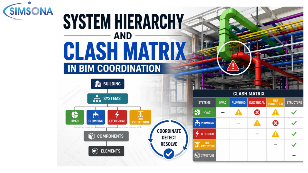
System Hierarchy and Clash Matrix in BIM Coordination

Introduction

Building Information Modeling (BIM) has transformed the Architecture, Engineering, and Construction (AEC) industry by enabling multidisciplinary teams to work within a coordinated digital environment. However, as projects become increasingly complex, simply creating 3D models is no longer sufficient. Effective BIM Coordination depends on two critical concepts: System Hierarchy and the Clash Matrix.

System hierarchy defines the order of importance among different building systems, while the clash matrix establishes which systems should be checked against one another during coordination. Together, they streamline the coordination process, reduce unnecessary clashes, improve decision-making, and prevent costly rework during construction.

This article explores both concepts in detail, their role in BIM workflows, and best practices for implementing them on construction projects in the United States.

What is BIM Coordination?

BIM Coordination is the process of integrating models from different disciplines—including architecture, structural engineering, mechanical, electrical, plumbing (MEP), fire protection, and specialty contractors—to identify and resolve conflicts before construction begins.

The primary objectives include:

  • Detecting physical clashes.
  • Resolving design conflicts.
  • Improving constructability.
  • Reducing RFIs.
  • Preventing change orders.
  • Enhancing project schedules.
  • Lowering construction costs.

Software such as Autodesk Navisworks, Solibri Office, Revizto, BIM Track, and ACC Model Coordination are commonly used during this process.

Understanding System Hierarchy

System hierarchy establishes the priority order among building systems during coordination.

Since multiple systems often compete for the same physical space, not every discipline can occupy its ideal location. A predefined hierarchy determines which systems maintain their position and which systems adjust around them.

Without a hierarchy, coordination meetings become subjective, leading to repeated model revisions and project delays.

Why System Hierarchy Matters

A clear system hierarchy helps teams:

  • Eliminate coordination confusion.
  • Minimize redesign efforts.
  • Reduce coordination meetings.
  • Speed up clash resolution.
  • Improve constructability.
  • Maintain installation sequencing.
  • Avoid field conflicts.

It creates consistency across every coordination session.

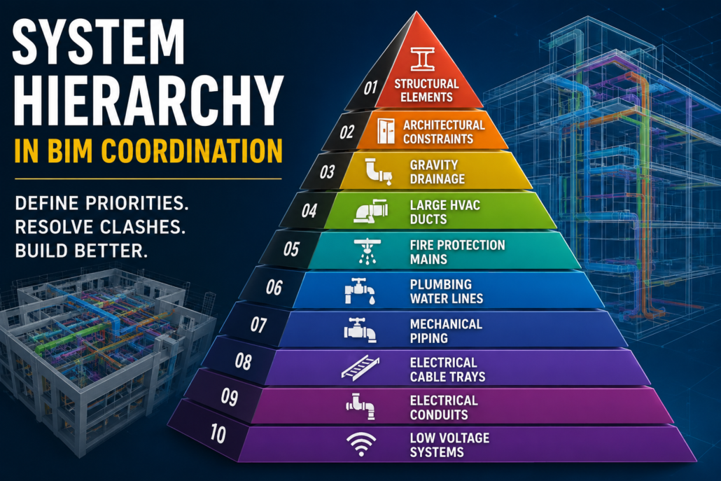
Typical Building System Hierarchy

Although every project has unique requirements, the following hierarchy is commonly used on commercial and institutional projects.

PrioritySystemReason
1Structural ElementsDifficult and expensive to relocate
2Architectural ConstraintsWalls, shafts, ceilings, façade
3Gravity DrainageRequires slope; limited flexibility
4Large HVAC DuctsHigh space requirements
5Fire Protection MainsMust maintain hydraulic performance
6Plumbing Water LinesModerate routing flexibility
7Mechanical PipingCan often reroute
8Electrical Cable TraysFlexible routing
9Electrical ConduitsHighly flexible
10Low Voltage SystemsMost flexible

This hierarchy may vary depending on project type.

Example of System Hierarchy

Imagine a hospital corridor where multiple services intersect.

The available ceiling space must accommodate:

  • Structural beam.
  • Supply air duct.
  • Fire sprinkler pipe.
  • Plumbing drain.
  • Electrical cable tray.
  • Data conduit.

Following hierarchy:

  • The beam remains fixed.
  • The gravity drain maintains its slope.
  • The HVAC duct adjusts slightly.
  • Fire protection reroutes around the duct.
  • Cable tray shifts.
  • Electrical conduits take the remaining available space.

This structured approach minimizes redesign.

What is a Clash Matrix?

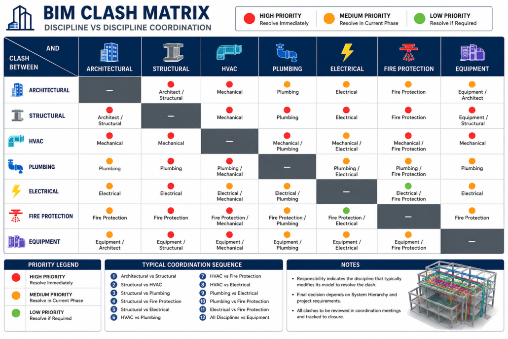
A Clash Matrix is a coordination planning document that defines:

  • Which disciplines are compared.
  • Which clashes are important.
  • Who is responsible.
  • Clash priority.
  • Coordination sequence.

Instead of checking every object against every other object, the clash matrix focuses on meaningful coordination tasks.

Benefits of a Clash Matrix

An organized clash matrix provides:

  • Faster clash detection.
  • Fewer false positives.
  • Better coordination meetings.
  • Clear discipline ownership.
  • Standardized workflows.
  • Reduced model processing time.
  • Improved reporting.

Sample Clash Matrix

Discipline ADiscipline BPriorityResponsible Team
StructuralHVACHighMechanical
StructuralPlumbingHighPlumbing
StructuralElectricalMediumElectrical
StructuralFire ProtectionHighFire Protection
HVACPlumbingHighMechanical & Plumbing
HVACElectricalMediumMechanical & Electrical
HVACFire ProtectionHighMechanical & Fire
PlumbingElectricalMediumPlumbing & Electrical
PlumbingFire ProtectionMediumPlumbing & Fire
ElectricalFire ProtectionLowElectrical & Fire

Not every clash carries the same importance.

Types of BIM Clashes

1. Hard Clash

A hard clash occurs when two physical objects occupy the same space.

Examples:

  • Duct passing through a beam.
  • Pipe intersecting a column.
  • Cable tray inside a wall.

These require immediate resolution.

2. Soft Clash (Clearance Clash)

Objects may not intersect physically but violate required clearance zones.

Examples:

  • Insufficient maintenance access around AHUs.
  • Inadequate clearance near electrical panels.
  • Restricted access to valves.

Soft clashes are critical for operations and maintenance.

3. Workflow Clash

Workflow clashes occur when installation sequencing becomes impossible.

Examples:

  • Equipment installed before access openings.
  • Pipe blocking future duct installation.
  • Ceiling installation preventing maintenance access.

These are increasingly important in 4D BIM planning.

Setting Up a Clash Matrix

A typical coordination workflow includes:

Step 1: Collect Discipline Models

Gather models from:

  • Architecture.
  • Structure.
  • HVAC.
  • Plumbing.
  • Electrical.
  • Fire Protection.
  • Civil.

Step 2: Clean Models

Before running clashes:

  • Remove duplicate objects.
  • Purge unused elements.
  • Verify coordinates.
  • Confirm shared origin.
  • Validate model versions.

Step 3: Define Coordination Zones

Split the building into manageable areas such as:

  • Basement.
  • Podium.
  • Floor 1.
  • Floor 2.
  • Roof.
  • Mechanical rooms.

This improves performance and organization.

Step 4: Create Clash Tests

Examples include:

  • Structure vs HVAC.
  • Structure vs Plumbing.
  • HVAC vs Electrical.
  • HVAC vs Fire Protection.
  • Plumbing vs Electrical.

Step 5: Apply Tolerances

Not every overlap is significant.

Typical tolerances include:

  • 5 mm.
  • 10 mm.
  • 20 mm.
  • Clearance offsets.

Proper tolerances reduce false clash reports.

Step 6: Assign Responsibilities

Each clash should include:

  • Responsible discipline.
  • Due date.
  • Status.
  • Comments.
  • Screenshot.
  • Location.

Step 7: Verify Resolution

After updates:

  • Re-run clash tests
  • Confirm resolution
  • Archive reports
  • Close issues

Coordination Meeting Workflow

A standard coordination meeting often follows this sequence:

  1. Review open clashes.
  2. Prioritize high-impact issues.
  3. Apply system hierarchy rules.
  4. Decide ownership.
  5. Assign corrective actions.
  6. Set deadlines.
  7. Re-test updated models.
  8. Document resolved issues.

Consistent documentation helps maintain accountability.

Common Coordination Challenges

Projects frequently encounter:

  • Outdated discipline models.
  • Inconsistent naming conventions.
  • Incorrect project coordinates.
  • Excessive duplicate clashes.
  • Undefined ownership.
  • Missing model updates.
  • Poor communication.
  • Lack of established hierarchy.

Addressing these issues early improves coordination efficiency.

Best Practices for Effective BIM Coordination

To maximize the benefits of system hierarchy and clash matrices:

  • Define system hierarchy during the BIM Execution Plan (BEP).
  • Agree on a standardized clash matrix before design coordination begins.
  • Use consistent naming conventions across all models.
  • Establish shared coordinates and model origins.
  • Run clash detection regularly rather than waiting for major milestones.
  • Focus on high-priority clashes before addressing minor issues.
  • Track issues using BIM collaboration platforms such as Autodesk Construction Cloud or BIM Track.
  • Archive coordination reports for future reference and quality assurance.
  • Include subcontractors early to improve constructability.
  • Review clash trends to identify recurring design problems.

Applications Across Different Project Types

Different facilities require customized coordination strategies:

  • Healthcare: High density of MEP systems, medical gases, and strict maintenance clearances.
  • Commercial Offices: Extensive HVAC, electrical, and IT infrastructure requiring disciplined ceiling coordination.
  • Industrial Facilities: Large process piping and equipment demand rigorous system hierarchy.
  • Residential Towers: Efficient coordination of plumbing stacks, electrical risers, and HVAC systems across repetitive floors.
  • Airports and Transportation Hubs: Complex multidisciplinary coordination with extensive fire protection, security, and communication systems.

Conclusion

System hierarchy and clash matrices are fundamental to successful BIM coordination. Rather than relying on reactive problem-solving during construction, they provide a structured framework for resolving conflicts in the digital model, where changes are faster, less expensive, and easier to manage.

By establishing clear priorities for building systems and defining targeted clash detection workflows, project teams can reduce design conflicts, improve collaboration, accelerate construction schedules, and deliver higher-quality buildings. As BIM adoption continues to grow across the U.S. construction industry, mastering these coordination tools is becoming an essential skill for architects, engineers, contractors, and BIM managers alike.

Modern Building Code Compliance: The BIM Advantage

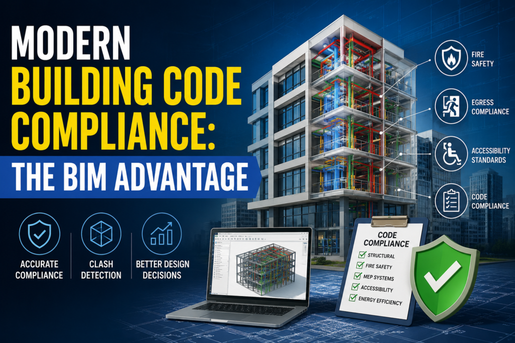
Modern Building Code Compliance

Introduction

Building code compliance has always been one of the most critical aspects of the U.S. construction industry. From structural integrity and fire safety to accessibility and energy efficiency, every project must meet a complex network of federal, state, and local regulations before receiving approval. Traditionally, compliance has been viewed as a documentation exercise—checking boxes, reviewing drawings manually, and correcting issues during permit reviews.

However, modern construction has fundamentally changed this perspective.

Today’s commercial buildings, hospitals, airports, residential towers, manufacturing plants, and mixed-use developments are far more sophisticated than ever before. As project complexity increases, building code compliance is no longer just about completing a checklist—it has become an integrated design process that begins in the earliest stages of planning.

For construction projects across the United States, BIM has become one of the most effective tools for reducing compliance risks, minimizing costly redesigns, accelerating approvals, and improving project quality.

Why Traditional Code Compliance Is No Longer Enough

Historically, code compliance involved reviewing hundreds of pages of construction drawings against local regulations.

Design teams manually checked:

  • Fire exits.
  • Occupancy limits.
  • Corridor widths.
  • Stair dimensions.
  • Structural requirements.
  • Accessibility standards.
  • Mechanical ventilation.
  • Plumbing layouts.
  • Electrical safety.

This process worked reasonably well for smaller buildings.

Today’s projects are dramatically different.

Modern facilities often contain:

  • Thousands of rooms.
  • Millions of model elements.
  • Complex MEP systems.
  • Multiple occupancy classifications.
  • Sustainable building requirements.
  • Smart building technologies.
  • Modular construction components.

A manual checklist simply cannot keep pace with this level of complexity.

The Growing Complexity of U.S. Building Codes

Unlike many countries with a single national building code, the United States operates under multiple regulatory frameworks.

Projects may need to comply with:

  • International Building Code (IBC).
  • International Residential Code (IRC).
  • International Fire Code (IFC).
  • International Existing Building Code (IEBC).
  • International Energy Conservation Code (IECC).
  • National Fire Protection Association (NFPA) standards.
  • Americans with Disabilities Act (ADA).
  • OSHA safety requirements.
  • Local municipal amendments.
  • State-specific building regulations.

In many jurisdictions, cities adopt different versions of these codes while introducing their own amendments.

For example:

A healthcare project in California may have different compliance requirements than a similar facility in Texas or Florida.

Managing these differences manually introduces significant risk.

Why Compliance Starts During Design

One of the biggest misconceptions is that code compliance occurs after the design is complete.

In reality, compliance begins during conceptual planning.

Design decisions affecting compliance include:

  • Building height.
  • Occupancy classification.
  • Fire separation.
  • Means of egress.
  • Structural systems.
  • Elevator placement.
  • Accessibility routes.
  • Mechanical ventilation.
  • Emergency exits.
  • Parking layouts.

Changing these elements after permit submission often leads to:

  • Design revisions.
  • Permit delays.
  • Additional consultant fees.
  • Construction schedule impacts.
  • Increased project costs.

BIM allows these issues to be identified before they become expensive problems.

How BIM Changes the Compliance Process

Building Information Modeling creates an intelligent digital representation of the building instead of isolated drawings.

Every component contains information such as:

  • Dimensions.
  • Materials.
  • Fire ratings.
  • Manufacturer data.
  • Structural properties.
  • Mechanical specifications.
  • Accessibility clearances.

Because every discipline works within a coordinated model, compliance can be reviewed continuously rather than only at project completion.

This proactive approach reduces the likelihood of errors and improves coordination across architectural, structural, and MEP teams.

Automated Rule-Based Code Checking

One of BIM’s greatest advantages is its ability to support automated code validation.

Instead of manually measuring hundreds of spaces, software can evaluate the model against predefined rules.

Examples include:

Corridor Width Verification

BIM can identify corridors that do not meet minimum width requirements based on occupancy.

Door Clearance

Models can verify required maneuvering clearances for ADA compliance.

Ceiling Height Validation

Software can automatically detect spaces below minimum code requirements.

Exit Distance Analysis

Emergency travel distances can be analyzed throughout the building.

Fire Separation

Fire-rated walls, floors, and partitions can be validated against occupancy requirements.

Occupancy Calculations

Room areas and occupant loads can be automatically generated.

Instead of reviewing thousands of dimensions manually, design teams receive immediate notifications about potential violations.

BIM Improves Multidisciplinary Coordination

Building codes rarely affect only one discipline.

For example:

An architect may design an accessible corridor.

A structural engineer may introduce columns that reduce its width.

An HVAC engineer may route ductwork through required clearance zones.

An electrical engineer may position equipment that blocks emergency access.

Without coordination, these conflicts often remain hidden until construction.

BIM enables every discipline to work within a shared digital environment, allowing issues to be resolved before construction begins.

Clash Detection Prevents Compliance Problems

Clash detection is commonly associated with reducing construction conflicts, but it also supports regulatory compliance.

Examples include:

  • Fire sprinklers intersecting structural beams
  • HVAC ducts blocking fire dampers
  • Electrical conduits conflicting with accessible ceiling heights
  • Plumbing systems interfering with required clearances
  • Structural members obstructing egress routes

By resolving these issues early, projects avoid costly field modifications and improve compliance.

Supporting ADA Accessibility Requirements

Accessibility is one of the most important compliance areas in U.S. construction.

BIM enables teams to verify:

  • Wheelchair turning radii.
  • Accessible entrances.
  • Ramp slopes.
  • Elevator dimensions.
  • Door clearances.
  • Restroom layouts.
  • Accessible parking.
  • Reach ranges.
  • Accessible routes.

Instead of relying solely on manual drafting reviews, designers can validate accessibility throughout the project lifecycle.

Enhancing Fire and Life Safety Planning

Fire safety involves much more than placing fire extinguishers or exit signs.

BIM supports planning for:

  • Fire-rated assemblies.
  • Smoke compartments.
  • Occupant evacuation paths.
  • Emergency access routes.
  • Stair pressurization systems.
  • Fire sprinkler coordination.
  • Fire alarm system integration.
  • Emergency lighting.

Three-dimensional visualization also helps stakeholders understand evacuation strategies more effectively than traditional 2D drawings.

Energy Code Compliance Through BIM

Modern U.S. projects must increasingly satisfy stringent energy efficiency requirements.

BIM supports compliance by enabling:

  • Building envelope analysis.
  • Thermal performance studies.
  • Daylighting simulations.
  • HVAC performance evaluation.
  • Energy consumption modeling.
  • Solar exposure analysis.
  • Building orientation optimization.

These capabilities help teams meet evolving energy codes while supporting sustainability goals.

Better Documentation for Permit Approvals

Permit reviewers often receive thousands of drawing sheets.

BIM-generated documentation offers several advantages:

  • Consistent drawing sets.
  • Coordinated schedules.
  • Accurate quantities.
  • Automatic updates.
  • Fewer documentation inconsistencies.
  • Better visualization.
  • Improved review efficiency.

Because drawings are generated from a single coordinated model, revisions are propagated throughout the documentation set, reducing the risk of conflicting information.

Reducing Rework During Construction

Many compliance issues discovered in the field result in:

  • Demolition.
  • Redesign.
  • Material waste.
  • Labor delays.
  • Inspection failures.
  • Change orders.

BIM helps identify potential issues before construction begins, allowing teams to resolve them digitally instead of physically.

This shift reduces costs while improving project schedules.

Digital Twins and Ongoing Compliance

Compliance does not end when construction is complete.

Facility owners must continue meeting operational requirements throughout a building’s lifecycle.

BIM models increasingly serve as the foundation for digital twins, supporting:

  • Facility maintenance.
  • Fire safety inspections.
  • Equipment replacement.
  • Space management.
  • Renovation planning.
  • Asset tracking.
  • Emergency response planning.

Maintaining an accurate digital model makes future renovations and code upgrades significantly more manageable.

The Future of Code Compliance

The construction industry is moving toward increasingly digital approval processes.

Emerging technologies include:

  • AI-assisted code checking.
  • Machine learning for design validation.
  • Cloud-based BIM collaboration.
  • Automated permit review workflows.
  • Digital building twins.
  • Reality capture integration.
  • Rule-based compliance engines.

As regulatory requirements continue to evolve, BIM will play an even greater role in ensuring projects meet safety, sustainability, and performance standards.

Benefits of BIM for Building Code Compliance

Organizations adopting BIM for compliance can achieve several advantages:

  • Earlier identification of code violations.
  • Improved collaboration across project teams.
  • Reduced design conflicts.
  • Faster permit approvals.
  • Lower construction rework costs.
  • Better documentation accuracy.
  • Enhanced accessibility verification.
  • Improved fire and life safety planning.
  • Greater confidence in regulatory compliance.
  • Better lifecycle management after project completion.

Conclusion

Building code compliance in the United States has evolved far beyond completing regulatory checklists. As buildings become more complex and codes continue to expand, traditional manual review methods are increasingly insufficient. Modern compliance requires continuous coordination, accurate information, and early validation throughout the design and construction process.

Building Information Modeling (BIM) enables this shift by integrating code considerations directly into the digital design workflow. Through coordinated models, automated rule-based checking, clash detection, accessibility validation, and multidisciplinary collaboration, BIM helps project teams identify and resolve compliance issues before they affect schedules, budgets, or construction quality.

For architects, engineers, contractors, and owners, BIM is no longer simply a design technology—it is a strategic approach to delivering safer, more efficient, and code-compliant buildings. In an industry where regulatory requirements continue to evolve, adopting BIM-driven compliance processes is becoming essential for successful project delivery across the United States.

Open BIM vs Closed BIM: Which Approach Is Better?

Open bim vs Closed bim

Introduction

Building Information Modeling (BIM) has become the foundation of modern construction in the United States, enabling architects, engineers, contractors, fabricators, and facility managers to collaborate on increasingly complex projects. From high-rise commercial buildings and healthcare facilities to airports, educational campuses, and industrial plants, BIM has transformed how buildings are designed, coordinated, constructed, and managed.

However, as BIM adoption continues to grow across the U.S. Architecture, Engineering, and Construction (AEC) industry, one important question continues to shape project workflows:

Should project teams adopt Open BIM or Closed BIM?

The answer is not always straightforward. Some organizations prefer proprietary software ecosystems that offer seamless integration within a single platform, while others prioritize interoperability and open standards that allow multiple software applications to work together.

Understanding the differences between Open BIM and Closed BIM is essential for project owners, architects, engineers, contractors, and BIM managers seeking to maximize collaboration, reduce project risks, and improve long-term asset management.

This article explores Open BIM vs Closed BIM in the context of the U.S. construction industry, highlighting their advantages, limitations, and the factors that influence which approach is best for different project types.

Understanding BIM Collaboration

BIM is more than creating intelligent 3D models. It is a collaborative process where multiple disciplines contribute specialized information to develop a coordinated digital representation of a building.

Typical project participants include:

  • Architects.
  • Structural engineers.
  • Mechanical engineers.
  • Electrical engineers.
  • Plumbing consultants.
  • Fire protection designers.
  • Civil engineers.
  • Steel detailers.
  • Contractors.
  • Fabricators.
  • Facility managers.

Because these stakeholders often use different software platforms, the ability to exchange accurate project information becomes critical.

This is where Open BIM and Closed BIM differ significantly.

What Is Open BIM?

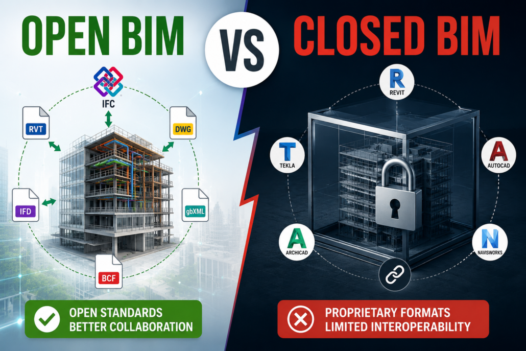
Open BIM is a collaborative approach based on open, vendor-neutral standards that allow project data to be shared across different BIM software applications.

Instead of requiring every participant to use the same software, Open BIM enables teams to exchange information using standardized file formats such as:

  • IFC (Industry Foundation Classes).
  • BCF (BIM Collaboration Format).
  • COBie (Construction Operations Building Information Exchange).

This flexibility allows each organization to continue using the software best suited to its discipline while maintaining interoperability across the project.

What Is Closed BIM?

Closed BIM refers to workflows where project teams primarily use software products from the same vendor or within a proprietary ecosystem.

Because applications are designed to work together, data exchange is generally more seamless, reducing the need for file conversions or interoperability standards.

For example, a project team may use a single software ecosystem for:

  • Architectural modeling.
  • Structural modeling.
  • MEP design.
  • Quantity takeoffs.
  • Clash detection.
  • Construction documentation.
  • Project coordination.

Closed BIM focuses on maximizing integration within a controlled software environment.

Why This Matters in the U.S. Construction Industry

Construction projects in the United States often involve dozens—or even hundreds—of companies working together.

A typical commercial project may include:

  • An architect using one BIM platform.
  • Structural consultants using another.
  • Steel fabricators using specialized detailing software.
  • MEP contractors using fabrication tools.
  • Facility managers requiring asset management systems.

If project information cannot move efficiently between these systems, teams may experience:

  • Data loss.
  • Duplicate modeling.
  • Coordination errors.
  • Delayed approvals.
  • Increased project costs.

Selecting the right BIM strategy is therefore essential for project success.

Open BIM Advantages

Greater Software Flexibility

One of the biggest strengths of Open BIM is freedom of choice.

Every project participant can use software that best fits their expertise without forcing the entire team into a single software ecosystem.

This flexibility is particularly valuable on large U.S. infrastructure and public-sector projects where consultants often work with different technology platforms.

Improved Collaboration

Open standards encourage collaboration among multiple organizations.

Rather than recreating models from scratch, participants can exchange information throughout the project lifecycle.

This reduces:

  • Duplicate work.
  • Manual data entry.
  • Communication gaps.
  • Coordination delays.

Long-Term Data Accessibility

Buildings often remain in service for 50 years or more.

Software vendors and file formats may change over time.

Open BIM helps preserve project information by storing data in internationally recognized formats rather than relying exclusively on proprietary software.

This is especially valuable for facility management and future renovations.

Better Support for Public Projects

Many U.S. government agencies and public institutions increasingly encourage or require open data standards to ensure long-term accessibility and avoid vendor lock-in.

Open BIM provides greater transparency for owners managing public assets.

Closed BIM Advantages

Seamless Software Integration

Because applications within the same ecosystem are designed to work together, data exchange is generally smoother.

Benefits include:

  • Faster synchronization.
  • Fewer import/export issues.
  • Consistent object behavior.
  • Simplified workflows.

For teams already standardized on one software platform, Closed BIM can improve day-to-day productivity.

Easier Training and Support

Organizations using a single software ecosystem often benefit from:

  • Standardized workflows.
  • Consistent user interfaces.
  • Unified technical support.
  • Simplified employee training.

This can reduce onboarding time for new team members.

Faster Project Coordination

When all disciplines work in the same environment, coordination becomes more efficient.

Changes made by one team are often reflected more quickly across related models, reducing coordination delays.

Better Native Functionality

Native software files generally retain:

  • Parametric relationships.
  • Families and components.
  • Material properties.
  • Constraints.
  • Intelligent object behavior.

Some of this information may be simplified when exported to open exchange formats.

Comparing Open BIM and Closed BIM

FeatureOpen BIMClosed BIM
Software flexibilityExcellentLimited
Vendor independenceHighLow
InteroperabilityHighModerate
Native software performanceModerateExcellent
Collaboration across organizationsExcellentGood
Long-term data accessibilityExcellentModerate
Training simplicityModerateExcellent
Vendor lock-inMinimalHigher
Public-sector suitabilityExcellentGood
Multi-software coordinationExcellentLimited

Common Challenges with Open BIM

Although Open BIM offers significant advantages, it is not without challenges.

Some exported models may experience:

  • Missing object properties.
  • Geometry translation issues.
  • Reduced parametric intelligence.
  • Classification inconsistencies.
  • Mapping errors between software platforms.

These issues are becoming less common as interoperability standards continue to improve, but careful quality control remains essential.

Challenges with Closed BIM

Closed BIM environments also present limitations.

Organizations may encounter:

  • Dependence on a single software vendor.
  • Higher licensing costs.
  • Limited flexibility when hiring consultants.
  • Difficulty collaborating with external partners using different platforms.
  • Long-term concerns regarding proprietary data formats.

For projects involving multiple independent firms, these limitations can become significant.

Open BIM and U.S. Design-Build Projects

Design-build delivery continues to expand across the United States.

These projects emphasize collaboration between designers and contractors from the earliest project stages.

Open BIM supports this approach by allowing each participant to contribute using their preferred software while maintaining coordinated project information.

This flexibility is particularly valuable on large commercial developments, transportation projects, healthcare facilities, and industrial construction.

Open BIM for Facility Management

Owners increasingly expect BIM models to deliver value long after construction ends.

Open BIM supports facility management through standardized data that can integrate with:

  • Computerized Maintenance Management Systems (CMMS).
  • Building Management Systems (BMS).
  • Digital twins.
  • Asset management platforms.
  • Space management software.

Vendor-neutral data improves long-term usability throughout the building lifecycle.

When Closed BIM May Be the Better Choice

Closed BIM can be highly effective when:

  • All consultants use the same software platform.
  • Projects are relatively small or medium in scale.
  • Teams require maximum native software functionality.
  • Organizations have standardized workflows.
  • Long-term interoperability is not a primary concern.

Many private developers successfully use Closed BIM because of its simplicity and efficient coordination within established software ecosystems.

When Open BIM Is the Better Choice

Open BIM is generally the preferred approach when:

  • Multiple organizations use different BIM software.
  • Public-sector projects require open standards.
  • Long-term asset management is important.
  • Facility owners want vendor-neutral building data.
  • International consultants are involved.
  • Teams prioritize flexibility and collaboration over software standardization.

Large U.S. infrastructure, healthcare, airport, university, and government projects frequently benefit from Open BIM workflows.

Best Practices for Successful BIM Collaboration

Regardless of whether a project uses Open BIM or Closed BIM, success depends on clear planning and coordination.

Recommended practices include:

  • Develop a comprehensive BIM Execution Plan (BEP).
  • Establish file naming and version control standards.
  • Define responsibilities for each discipline.
  • Perform regular model coordination and clash detection.
  • Validate exchanged models before coordination meetings.
  • Maintain consistent object classifications.
  • Schedule periodic quality assurance reviews.

These practices help reduce errors and improve collaboration across the project lifecycle.

The Future of BIM in the United States

The U.S. construction industry is moving toward greater interoperability as digital project delivery becomes standard practice. Emerging technologies such as cloud-based collaboration, digital twins, artificial intelligence, and automated code checking all depend on reliable information exchange between different software platforms.

Rather than viewing Open BIM and Closed BIM as competing approaches, many organizations are adopting hybrid workflows. They use proprietary software for modeling and discipline-specific tasks while relying on open standards like IFC and COBie for collaboration, project handover, and facility management. This balanced strategy combines the efficiency of native software with the flexibility of vendor-neutral data exchange.

Conclusion

The choice between Open BIM and Closed BIM depends on project goals, team structure, owner requirements, and long-term asset management needs. Closed BIM offers streamlined workflows, seamless software integration, and excellent native functionality for teams working within a single software ecosystem. Open BIM, on the other hand, promotes interoperability, vendor independence, and collaboration across diverse software platforms, making it particularly valuable for large, multidisciplinary projects in the United States.

As the U.S. AEC industry embraces digital transformation, interoperability is becoming a strategic advantage rather than a technical preference. Organizations that understand when to use Open BIM, Closed BIM, or a hybrid approach will be better equipped to deliver efficient, coordinated, and future-ready construction projects while meeting the evolving demands of owners, contractors, and facility managers.

BIM Is Not Just Revit: Difference Between Design and BIM

BIM Is Not Just Revit

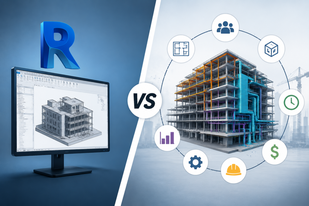
One of the biggest misconceptions in the architecture, engineering, and construction (AEC) industry is the belief that Building Information Modeling (BIM) is simply another name for Revit. It’s a misunderstanding that often leads to confusion among students, clients, and even professionals entering the industry.

Statements like “We need Revit drawings for BIM” or “We already use BIM because we work in Revit” are heard frequently. While Revit is undoubtedly one of the most powerful BIM software platforms available today, BIM is much more than a software application. It is a collaborative process, a methodology, and a data-driven approach to designing, constructing, and managing buildings throughout their lifecycle.

Understanding the distinction between design software and BIM processes is essential for architects, engineers, contractors, developers, and facility managers. This article explains what BIM truly is, how it differs from traditional design, why Revit is only one component of BIM, and how organizations can fully benefit from adopting BIM methodologies.

What Is BIM?

Building Information Modeling (BIM) is a digital process for creating, managing, and sharing information about a built asset throughout its entire lifecycle—from concept and design to construction, operation, maintenance, renovation, and even demolition.

Unlike traditional CAD drafting, BIM creates an intelligent digital representation of a building where every element contains information, not just geometry.

A BIM model includes:

  • Architectural components.
  • Structural systems.
  • Mechanical systems.
  • Electrical systems.
  • Plumbing systems
  • Material specifications.
  • Product manufacturers.
  • Cost information.
  • Construction sequencing.
  • Maintenance data.
  • Performance information.

In simple terms, BIM combines 3D geometry with intelligent data, enabling every stakeholder to work from the same source of information.

What Is Revit?

Revit is a software application developed by Autodesk for creating intelligent 3D building models.

It enables professionals to:

  • Design buildings.
  • Produce construction documentation.
  • Generate schedules.
  • Coordinate disciplines.
  • Create parametric families.
  • Perform quantity take-offs.

Revit is one of the most widely used BIM-authoring tools in the world, but it is still only a tool.

Just as Microsoft Word is not the same as writing, Revit is not the same as BIM.

Design vs BIM: Understanding the Core Difference

Traditional design focuses primarily on creating drawings and communicating design intent. BIM, on the other hand, focuses on creating a coordinated digital information model that supports the entire project lifecycle.

Traditional design typically answers questions such as:

  • What does the building look like?
  • How should it be built?
  • What dimensions should contractors follow?

BIM goes much further by answering questions like:

  • What materials are used?
  • Who manufactures each component?
  • How much will it cost?
  • When should it be installed?
  • How will it perform?
  • How should it be maintained?
  • What happens when it is replaced?

In other words, design is one phase of a project, while BIM manages information throughout the entire project lifecycle.

Why People Think BIM Means Revit

There are several reasons why the misconception exists.

Revit Popularized BIM

Revit became one of the first mainstream software platforms capable of producing intelligent building models. As its popularity grew, many professionals began using the terms Revit and BIM interchangeably.

Training Often Focuses on Software

Many courses teach students how to use Revit tools without explaining BIM standards, collaboration workflows, information management, or project delivery methods.

As a result, many professionals become proficient in Revit but never learn what BIM actually involves.

Clients Often Request “BIM Models”

Sometimes, clients request BIM but simply expect a Revit file, even though true BIM deliverables include coordinated information, documentation standards, and structured project data.

BIM Is a Process, Not a Software

Perhaps the simplest way to understand BIM is this:

Software enables BIM, but software alone is not BIM.

Many software platforms support BIM workflows, including:

  • Autodesk Revit.
  • Navisworks.
  • Civil 3D.
  • Tekla Structures.
  • Archicad.
  • Bentley OpenBuildings.
  • Vectorworks Architect.
  • Solibri.
  • Synchro.
  • Autodesk Construction Cloud.

Each serves a different purpose, from modeling and clash detection to construction sequencing, model validation, and facility management.

Together, these tools support a BIM process—but none of them individually is BIM.

Traditional CAD Workflow vs BIM Workflow

In a traditional CAD workflow, architects, structural engineers, and MEP consultants often create separate drawings with limited coordination. Any design change usually requires manual updates across multiple drawings, increasing the risk of inconsistencies.

In a BIM workflow, all disciplines develop coordinated intelligent models. Changes made to the model automatically update related plans, elevations, sections, schedules, and quantities. Coordination improves significantly because every stakeholder works with connected project information rather than isolated drawings.

The result is fewer errors, faster revisions, and better collaboration throughout the project.

BIM Is About Collaboration

One of BIM’s greatest strengths is collaborative working.

Instead of multiple disconnected teams producing separate documents, BIM enables everyone to work from coordinated information.

Stakeholders include:

  • Architects.
  • Structural engineers.
  • MEP engineers.
  • Contractors.
  • Fabricators.
  • Quantity surveyors.
  • Project managers.
  • Facility managers.
  • Owners.

Everyone contributes information that becomes part of a shared digital asset.

This collaborative environment reduces misunderstandings, improves communication, and minimizes project risks.

BIM Goes Beyond 3D Models

Many people assume BIM simply means creating a 3D model.

In reality, BIM extends into multiple dimensions.

3D BIM

Geometric representation of the building.

4D BIM

Construction scheduling linked to model elements.

5D BIM

Cost estimation and budgeting integrated with the model.

6D BIM

Sustainability analysis, energy performance, and lifecycle assessment.

7D BIM

Facility management, maintenance planning, and asset management.

These additional dimensions demonstrate that BIM is an information management process rather than just a modeling technique.

Can You Use Revit Without Doing BIM?

Yes.

Many organizations use Revit merely as a drafting tool.

Common examples include:

  • Creating 3D models solely for visualization.
  • Producing construction drawings without coordination.
  • Ignoring BIM standards.
  • Not sharing models between disciplines.
  • Excluding metadata from model elements.
  • Delivering only PDF drawings to clients.

In these cases, the organization is using Revit software but not fully implementing BIM.

Can BIM Exist Without Revit?

Absolutely.

Several organizations successfully implement BIM using other authoring tools such as Archicad, Tekla Structures, Bentley OpenBuildings, or Open BIM workflows based on Industry Foundation Classes (IFC).

The BIM methodology remains the same regardless of the software used.

This is why many government projects worldwide encourage or require open standards rather than dependence on a single software platform.

Key Components of a Successful BIM Process

A mature BIM implementation involves much more than creating models.

Successful BIM projects typically include:

  • BIM Execution Plans (BEP).
  • Employer’s Information Requirements (EIR).
  • Common Data Environment (CDE).
  • Naming conventions.
  • Model coordination.
  • Clash detection.
  • Information exchange standards.
  • Level of Information Need.
  • Quality assurance procedures.
  • Model validation.
  • Asset information management.
  • Digital handover documentation.

These processes ensure that information remains reliable, consistent, and useful throughout the project’s lifecycle.

Benefits of Implementing True BIM

Organizations that embrace BIM as a process rather than simply using modeling software gain significant advantages.

These include:

  • Improved collaboration across disciplines.
  • Better design coordination.
  • Early clash detection.
  • Reduced rework during construction.
  • Faster project delivery.
  • More accurate quantity take-offs.
  • Better cost control.
  • Enhanced project visualization.
  • Improved communication with clients.
  • More efficient facility management.
  • Higher-quality project documentation.
  • Better lifecycle asset management.

These benefits often translate into reduced project risk and long-term operational savings.

Common Myths About BIM

Myth 1: BIM Is Just Revit

Reality: Revit is one BIM-authoring tool. BIM is the overall process.

Myth 2: BIM Is Only 3D Modeling

Reality: BIM also includes information management, collaboration, scheduling, costing, and asset management.

Myth 3: BIM Is Only for Architects

Reality: BIM supports architects, engineers, contractors, owners, facility managers, and many other stakeholders.

Myth 4: BIM Ends After Construction

Reality: One of BIM’s greatest values is supporting building operations and maintenance long after construction is complete.

Myth 5: Learning Revit Means You Know BIM

Reality: Revit skills are valuable, but BIM also requires knowledge of standards, workflows, coordination, collaboration, and information management.

The Future of BIM

As digital construction continues to evolve, BIM is becoming the foundation for technologies such as Digital Twins, Artificial Intelligence, IoT-enabled smart buildings, robotics, reality capture, and cloud-based collaboration.

Future projects will increasingly rely on integrated information rather than isolated drawings. Professionals who understand BIM principles—not just software commands—will be better prepared for this transformation.

Conclusion

Revit has transformed the way buildings are modeled and documented, but it is important to recognize that Revit is a tool, while BIM is a comprehensive process. Confusing the two can limit the value organizations gain from digital construction.

True BIM is about creating reliable information, enabling collaboration, improving coordination, reducing project risks, and supporting the entire lifecycle of a building. Software like Revit plays a crucial role in this process, but successful BIM implementation also depends on standards, workflows, communication, and effective information management.

Structural BIM vs Structural Engineering: Understanding the Real Difference

Structural Engineering vs Structural BIM

Structural engineering and Structural BIM are often used together in modern construction projects, but they are not the same thing. Many clients, architects, contractors, and even engineering students mistakenly assume that creating a 3D structural model is equivalent to performing structural engineering. In reality, these are two distinct disciplines that complement each other throughout the design and construction process.

While structural engineering focuses on designing safe, stable, and code-compliant structures, Structural Building Information Modeling (BIM) transforms those engineering designs into intelligent digital models that support coordination, fabrication, construction, and facility management.

Understanding the difference between these two fields is essential for project owners, contractors, consultants, and anyone involved in the Architecture, Engineering, and Construction (AEC) industry.

What is Structural Engineering?

Structural engineering is a branch of civil engineering that deals with analyzing, designing, and ensuring the stability of buildings and infrastructure. Structural engineers determine how a structure will safely resist loads such as:

  • Dead loads.
  • Live loads.
  • Wind loads.
  • Earthquake loads.
  • Snow loads.
  • Soil pressure.
  • Temperature effects.

Their responsibility is to make sure that every structural component can safely carry the expected loads throughout the building’s lifespan.

Structural engineers use engineering principles, mathematical calculations, and structural analysis software to design:

  • Foundations.
  • Columns.
  • Beams.
  • Slabs.
  • Shear walls.
  • Roof systems.
  • Steel frames.
  • Reinforced concrete structures.
  • Bridges.
  • Industrial facilities.

Their final deliverables typically include:

  • Structural calculations.
  • Design reports.
  • Structural drawings.
  • Material specifications.
  • Reinforcement details.
  • Design assumptions.
  • Code compliance documentation.

The structural engineer is legally responsible for the safety and integrity of the structure.

What is Structural BIM?

Structural BIM (Building Information Modeling) is the process of creating an intelligent digital representation of the structural design developed by structural engineers.

Instead of producing only 2D drawings, Structural BIM converts engineering information into a data-rich 3D model that contains accurate geometry, materials, quantities, connections, and construction information.

The BIM model serves as a single source of truth for architects, MEP engineers, contractors, fabricators, quantity surveyors, and facility managers.

Structural BIM models include:

  • Concrete framing.
  • Steel framing.
  • Reinforcement (Rebar BIM).
  • Structural steel connections.
  • Precast elements.
  • Embedded components.
  • Openings.
  • Anchor bolts.
  • Base plates.
  • Structural assemblies.

Unlike engineering calculations, Structural BIM focuses on visualization, coordination, constructability, documentation, and digital collaboration.

Structural Engineering vs Structural BIM

Structural EngineeringStructural BIM
Designs the structureModels the structure
Performs calculationsCreates intelligent digital models
Determines member sizesRepresents member sizes accurately
Ensures structural safetyEnsures model accuracy and coordination
Uses engineering standardsUses BIM standards and modeling practices
Produces design calculationsProduces coordinated BIM models
Responsible for structural integrityResponsible for model quality and constructability
Focuses on analysisFocuses on information management
Uses structural analysis softwareUses BIM authoring software
Creates engineering drawingsCreates fabrication and coordination models

The Primary Objective of Structural Engineering

The goal of structural engineering is to answer questions such as:

  • Will this beam carry the load safely?
  • Is the foundation adequate?
  • How much reinforcement is required?
  • What steel section should be used?
  • Will the building survive an earthquake?
  • Does the design meet building codes?

Every decision is driven by engineering analysis and safety.

The Primary Objective of Structural BIM

Structural BIM answers a different set of questions:

  • Can every discipline coordinate effectively?
  • Are there any clashes?
  • Can the structure be fabricated accurately?
  • Is the reinforcement constructible?
  • Can quantities be extracted automatically?
  • Can construction sequencing be planned?
  • Can shop drawings be generated efficiently?

Structural BIM focuses on improving project delivery rather than performing engineering design.

Typical Workflow: Structural Engineering Comes First

In most construction projects, the process follows this sequence:

1. Architectural Design

The architect develops the building layout, floor plans, elevations, and overall design concept.

2. Structural Analysis

The structural engineer analyzes loads and designs the structural system.

3. Structural Design

The engineer finalizes member sizes, reinforcement requirements, and connection details.

4. Structural BIM Modeling

BIM specialists create an intelligent 3D model based on the approved structural drawings.

5. Clash Detection

The structural model is coordinated with architectural and MEP models to identify and resolve conflicts before construction.

6. Shop Drawings

Detailed fabrication and construction drawings are generated directly from the BIM model.

7. Quantity Takeoff

Accurate material quantities are extracted from the coordinated model for procurement and cost estimation.

8. Construction Support

The BIM model supports installation sequencing, progress tracking, and on-site coordination throughout the construction phase.

Skills Required for Structural Engineers

Structural engineers require expertise in:

  • Structural mechanics.
  • Reinforced concrete design.
  • Steel design.
  • Foundation engineering.
  • Earthquake engineering.
  • Wind engineering.
  • Finite Element Analysis (FEA).
  • Design codes (ACI, Eurocode, IS Codes, BS Codes, etc.).
  • Load calculations.
  • Structural optimization.

Common software includes:

  • ETABS.
  • STAAD.Pro.
  • SAP2000.
  • SAFE.
  • RISA.
  • RAM Structural System.
  • Robot Structural Analysis.

Skills Required for Structural BIM Professionals

Structural BIM specialists focus on digital modeling and coordination. Key skills include:

  • BIM modeling standards.
  • Structural detailing.
  • Steel detailing.
  • Rebar modeling.
  • Clash detection.
  • BIM coordination.
  • Level of Development (LOD).
  • Family creation.
  • Quantity extraction.
  • Shop drawing production.
  • Model validation.

Common software includes:

  • Autodesk Revit.
  • Tekla Structures.
  • Navisworks.
  • Autodesk Construction Cloud.
  • BIM Collaborate Pro.
  • Advance Steel.
  • Dynamo.
  • Solibri.
  • Revizto.

Structural BIM Is More Than 3D Modeling

One of the biggest misconceptions is that Structural BIM simply means creating a 3D model. In reality, a BIM model contains valuable information beyond geometry, such as:

  • Material grades.
  • Section properties.
  • Reinforcement specifications.
  • Connection details.
  • Fabrication data.
  • Element IDs.
  • Construction phases.
  • Cost information.
  • Installation sequences.
  • Maintenance data.

This information supports multiple project stages, from design coordination to long-term facility management.

Collaboration Between Structural Engineers and BIM Modelers

Successful construction projects rely on close collaboration between structural engineers and BIM professionals.

The structural engineer provides:

  • Structural calculations.
  • Member sizing.
  • Reinforcement design.
  • Connection requirements.
  • Design intent.

The Structural BIM modeler translates this information into an intelligent digital model that can be used by architects, MEP engineers, fabricators, and contractors. During coordination, BIM specialists identify clashes or constructability issues, which are then reviewed with the structural engineer to ensure any modifications maintain the design intent.

Benefits of Structural BIM

When implemented effectively, Structural BIM offers several advantages:

  • Improved multidisciplinary coordination.
  • Reduced construction errors.
  • Early clash detection.
  • More accurate quantity takeoffs.
  • Faster shop drawing production.
  • Better visualization for stakeholders.
  • Improved construction planning.
  • Enhanced collaboration among project teams.
  • Reduced material waste.
  • Greater project efficiency.

Can a Structural Engineer Be a Structural BIM Engineer?

Yes. Many professionals combine structural engineering expertise with BIM skills. A structural engineer who understands BIM can:

  • Create intelligent structural models.
  • Coordinate with other disciplines.
  • Review constructability
  • Generate fabrication drawings.
  • Support digital project delivery.

Similarly, experienced BIM professionals with a solid understanding of structural systems can become valuable members of multidisciplinary project teams. However, creating BIM models does not replace the need for licensed structural engineering when design calculations and code compliance are required.

Common Misconceptions

“Structural BIM designs buildings.”

No. Structural BIM represents and manages structural information but does not perform engineering design or calculations.

“A Revit model is enough for construction.”

Not necessarily. The model must accurately reflect approved engineering designs, be coordinated with other disciplines, and include the required Level of Development (LOD) before it is suitable for construction.

“Structural engineers and BIM modelers do the same job.”

No. Structural engineers are responsible for designing safe structures, while BIM modelers focus on creating coordinated digital representations that support construction and project delivery.

“3D modeling is the same as BIM.”

A 3D model shows geometry. BIM combines geometry with information, relationships, metadata, and workflows, making it a comprehensive digital representation of the project.

The Future of Structural Engineering and BIM

The construction industry is increasingly adopting digital workflows where structural engineering and BIM work hand in hand. Emerging technologies such as Digital Twins, Artificial Intelligence (AI), Generative Design, Reality Capture, and cloud-based collaboration platforms are reshaping how structures are designed, coordinated, and managed.

As projects become more complex, professionals who understand both engineering principles and BIM processes will be in high demand, helping teams deliver safer, more efficient, and better-coordinated buildings.

Conclusion

Structural engineering and Structural BIM are complementary disciplines, each playing a vital role in the success of a construction project. Structural engineers ensure that a building is safe, stable, and compliant with design codes through rigorous analysis and calculations. Structural BIM professionals transform those engineering decisions into intelligent digital models that improve coordination, documentation, fabrication, and construction.

Best BIM Strategies for Large-Scale Construction Projects

BIM strategies

Introduction

Large-scale construction projects such as airports, hospitals, industrial plants, commercial complexes, rail networks, and smart city developments involve thousands of interconnected components, multiple stakeholders, extensive documentation, and strict deadlines. Managing such complexity using traditional construction methods often leads to coordination issues, design conflicts, cost overruns, and project delays.

Building Information Modeling (BIM) has emerged as a transformative technology that helps project teams plan, design, construct, and manage large-scale developments more efficiently. BIM goes beyond 3D modeling by creating a centralized digital representation of a facility that contains geometric, technical, operational, and financial information. However, simply adopting BIM software is not enough. The success of BIM in large projects depends heavily on implementing the right strategies throughout the project lifecycle.

This article explores the best BIM strategies that can help stakeholders maximize efficiency, reduce risks, improve collaboration, and achieve successful outcomes in large-scale construction projects.

Establish a Clear BIM Execution Plan (BEP)

One of the most critical BIM strategies is developing a comprehensive BIM Execution Plan (BEP) at the beginning of the project. A BIM Execution Plan defines how BIM processes, standards, responsibilities, workflows, and deliverables will be managed throughout the project.

Large projects involve architects, structural engineers, MEP consultants, contractors, subcontractors, fabricators, and facility managers. Without clear BIM guidelines, each team may follow different modeling approaches, leading to inconsistencies and coordination challenges.

A well-prepared BEP should outline project objectives, modeling standards, file naming conventions, level of development (LOD) requirements, collaboration procedures, software platforms, clash detection schedules, and information exchange protocols. By establishing these guidelines early, all stakeholders work toward a common goal and maintain consistency throughout the project.

Define BIM Goals and Project Objectives Early

Before BIM implementation begins, project stakeholders should clearly identify what they expect to achieve through BIM. Different projects may have different objectives depending on their complexity and requirements.

For example, an airport project may prioritize multidisciplinary coordination and construction sequencing, while a hospital project may focus on facility management integration and MEP coordination. Defining BIM goals helps teams allocate resources effectively and measure project success.

Common BIM objectives include:

  • Improving design coordination.
  • Reducing construction errors.
  • Enhancing project visualization.
  • Improving scheduling accuracy.
  • Controlling project costs.
  • Supporting prefabrication.
  • Enhancing facility management.
  • Minimizing project risks.

Clearly defined objectives ensure that BIM efforts remain focused on delivering measurable value throughout the project lifecycle.

Develop a Common Data Environment (CDE)

A Common Data Environment (CDE) serves as the central platform where all project information is stored, managed, and shared. In large-scale projects, thousands of drawings, models, specifications, reports, and construction documents are generated.

Without a centralized system, teams often struggle with version control issues, duplicate files, and communication gaps. A CDE provides a single source of truth for all project stakeholders.

Benefits of a Common Data Environment include:

  • Real-time information sharing.
  • Improved document management.
  • Better version control.
  • Enhanced collaboration.
  • Reduced data duplication.
  • Faster decision-making.

Cloud-based BIM platforms allow geographically dispersed teams to access up-to-date project information from anywhere, significantly improving project coordination.

Implement Standardized Modeling Practices

Consistency is essential in large BIM projects. When multiple teams contribute to a project model, variations in modeling methods can create confusion and coordination issues.

Organizations should establish standardized modeling practices covering:

  • Model structure.
  • Object naming conventions.
  • Classification systems.
  • Layer management.
  • Family creation standards.
  • Parameter requirements.
  • Data input procedures.

Standardization improves model quality, enhances interoperability, and simplifies information exchange among project participants. It also helps maintain model accuracy throughout the project lifecycle.

Focus on Clash Detection and Coordination

Clash detection is one of the most valuable BIM applications for large-scale construction projects. Complex buildings often contain extensive structural, architectural, mechanical, electrical, plumbing, and fire protection systems that occupy limited space.

Without proper coordination, conflicts between building systems can lead to costly rework during construction. BIM allows project teams to identify and resolve clashes digitally before work begins on-site.

Effective clash detection strategies include:

  • Conducting regular coordination meetings.
  • Establishing clash priority levels.
  • Assigning responsibility for clash resolution.
  • Maintaining clash tracking logs.
  • Performing multidisciplinary reviews.

Early detection of conflicts reduces construction delays, minimizes rework costs, and improves overall project efficiency.

Utilize 4D BIM for Construction Scheduling

Large projects often involve complex construction sequences involving multiple contractors and activities occurring simultaneously. Traditional scheduling methods may not adequately visualize project progression.

4D BIM integrates the project schedule with the 3D model, creating a time-based simulation of construction activities. This enables stakeholders to visualize construction sequences before execution.

Benefits of 4D BIM include:

  • Improved schedule planning.
  • Enhanced site logistics management.
  • Better resource allocation.
  • Identification of scheduling conflicts.
  • Improved stakeholder communication.

Construction teams can analyze different sequencing scenarios and optimize project schedules to minimize delays and maximize productivity.

Leverage 5D BIM for Cost Management

Cost overruns remain one of the biggest challenges in large-scale construction projects. 5D BIM integrates cost information with BIM models, enabling real-time quantity takeoffs and cost analysis.

As design changes occur, associated quantities and costs are automatically updated, allowing project teams to monitor budget impacts instantly.

Advantages of 5D BIM include:

  • Accurate quantity estimation.
  • Real-time cost tracking.
  • Better budget forecasting.
  • Improved procurement planning.
  • Enhanced financial transparency.

This approach enables stakeholders to make informed decisions while maintaining control over project finances.

Promote Early Stakeholder Involvement

Successful BIM implementation requires collaboration among all project participants from the earliest stages of project development.

Traditionally, contractors and specialty trades become involved after design completion. However, BIM encourages integrated project delivery by involving key stakeholders during design development.

Early stakeholder involvement helps:

  • Improve constructability reviews.
  • Enhance design quality.
  • Reduce project risks.
  • Identify cost-saving opportunities.
  • Streamline project coordination.

When architects, engineers, contractors, and facility managers collaborate early, they can identify and resolve potential issues before construction begins.

Integrate BIM with Prefabrication and Modular Construction

Prefabrication and modular construction are becoming increasingly popular in large projects due to their ability to improve quality and reduce construction time.

BIM provides highly accurate digital models that support off-site manufacturing processes. Detailed BIM models help fabricators produce components with precise dimensions and specifications.

Applications include:

  • Structural steel fabrication.
  • Rebar detailing.
  • MEP modular systems.
  • Precast concrete elements.
  • Modular building units.

Integration between BIM and prefabrication improves accuracy, reduces waste, and accelerates project delivery.

Implement BIM-Based Quality Control Procedures

Maintaining quality across a large project requires systematic monitoring and verification processes. BIM can support quality control by providing accurate digital representations of project components.

Quality control strategies include:

  • Model validation procedures.
  • Automated rule-based checking.
  • Design compliance reviews.
  • Construction verification processes.
  • As-built model updates.

Regular model audits help identify inconsistencies, missing information, and modeling errors before they impact construction activities.

Use BIM for Site Logistics Planning

Large construction sites often face challenges related to material storage, equipment movement, worker safety, and site access.

BIM enables teams to create detailed site logistics models that simulate construction activities and temporary site conditions.

Benefits include:

  • Optimized material storage locations.
  • Improved crane positioning.
  • Enhanced traffic management.
  • Better safety planning.
  • Efficient workspace allocation.

Visual site planning improves operational efficiency and reduces potential disruptions during construction.

Incorporate Reality Capture Technologies

Reality capture technologies such as laser scanning, drones, and photogrammetry can significantly enhance BIM workflows in large-scale projects.

These technologies provide accurate existing site conditions and support ongoing construction monitoring.

Applications include:

  • Existing condition documentation.
  • Construction progress tracking.
  • As-built verification.
  • Quality inspections.
  • Deformation monitoring.

Integrating reality capture data with BIM improves accuracy and ensures that project models reflect actual site conditions.

Adopt Open BIM and Interoperability Standards

Large projects often involve multiple software platforms used by different stakeholders. Interoperability challenges can create data exchange problems and information loss.

Open BIM standards such as IFC (Industry Foundation Classes) facilitate seamless communication between various BIM software applications.

Benefits of Open BIM include:

  • Improved collaboration.
  • Reduced software dependency.
  • Better information exchange.
  • Enhanced project flexibility.
  • Long-term data accessibility.

Open standards ensure that project information remains usable throughout the building lifecycle.

Train Teams and Build BIM Competency

Even the most advanced BIM technologies cannot deliver value without skilled professionals who understand how to use them effectively.

Organizations should invest in continuous BIM training programs covering:

  • BIM software skills.
  • Modeling standards.
  • Coordination processes.
  • Data management practices.
  • Emerging BIM technologies.

Developing BIM expertise across the project team improves adoption rates and maximizes the benefits of BIM implementation.

Utilize BIM for Facility Management

The value of BIM extends beyond construction completion. Large facilities require efficient operation and maintenance throughout their lifecycle.

6D BIM integrates asset information, maintenance schedules, equipment specifications, and operational data into the BIM model.

Facility managers can use BIM to:

  • Track building assets.
  • Schedule maintenance activities.
  • Manage space utilization.
  • Access equipment information.
  • Support renovation projects.

This approach improves long-term building performance and reduces operational costs.

Monitor BIM Performance Using Key Metrics

To ensure BIM strategies are delivering expected results, project teams should establish measurable performance indicators.

Common BIM Key Performance Indicators (KPIs) include:

  • Number of clashes identified and resolved.
  • Reduction in rework costs.
  • Schedule performance improvements.
  • Cost savings achieved.
  • Model accuracy levels.
  • Information delivery compliance.
  • Stakeholder satisfaction.

Regular performance monitoring helps organizations continuously improve their BIM processes and achieve greater project success.

Conclusion

Large-scale construction projects demand advanced management approaches capable of handling immense complexity, multiple stakeholders, and substantial financial investments. BIM provides a powerful framework for improving collaboration, reducing risks, enhancing design quality, controlling costs, and optimizing construction workflows.

The most effective BIM strategies include establishing a clear BIM Execution Plan, defining project objectives, creating a Common Data Environment, implementing standardized modeling practices, conducting regular clash detection, leveraging 4D and 5D BIM, integrating prefabrication, adopting interoperability standards, and utilizing BIM throughout the facility lifecycle.

When implemented strategically, BIM becomes far more than a modeling tool—it becomes a comprehensive project management platform that enables successful delivery of complex construction projects while improving efficiency, quality, and long-term asset performance.

Architectural BIM: From Conceptual Design to Fabrication Model || Simsona

	
Architectural BIM Across Different Project Stages:

Introduction 

Architectural Building Information Modeling (Architectural BIM) has fundamentally transformed the way buildings are designed, coordinated, and constructed. Rather than functioning as a simple three-dimensional drafting tool, Architectural BIM creates an intelligent digital representation of a building that evolves throughout the project lifecycle. Every wall, floor, roof, window, door, and architectural element contains geometric as well as non-geometric information that supports planning, visualization, analysis, coordination, estimation, documentation, and construction. 

One of the greatest strengths of Architectural BIM is that the model develops progressively alongside the design process. During the initial concept stage, the model contains only the information necessary to explore design ideas and building massing. As the project advances, the model gradually incorporates more accurate dimensions, material specifications, construction details, and fabrication information. This gradual refinement ensures that project teams always work with the appropriate level of information for each phase without unnecessarily increasing modeling complexity. The evolution of an architectural BIM model is commonly understood through four major stages: Schematic Design (Conceptual Geometry), Design Development (Approximate Geometry), Construction Documents (Specific Geometry), and Construction Model (Fabrication Model). Each stage serves a unique purpose while contributing to the development of a coordinated and constructible building. 

Schematic Design (Conceptual Geometry) 

The schematic design phase represents the beginning of the architectural design process, where ideas are translated into visual concepts and preliminary building forms. At this stage, the primary objective is not to define construction details but to establish the overall design intent of the project. Architects focus on understanding the client’s requirements, site conditions, functional relationships between spaces, and the general appearance of the proposed building. The BIM model developed during this phase consists of conceptual geometry, which emphasizes simplicity and flexibility rather than precise construction information. 

Conceptual geometry typically includes building masses, preliminary floor layouts, generic walls, roofs, circulation paths, and rough spatial arrangements. These elements are intentionally simplified because the design is expected to undergo multiple revisions before becoming finalized. Instead of concentrating on wall assemblies or window frame profiles, architects use basic shapes to study the building’s proportions, orientation, height, and interaction with the surrounding environment. This allows the design team to evaluate several alternatives quickly without investing time in unnecessary detailing. 

Although the geometry remains simple, the BIM model already contains valuable project information. Room names, approximate floor areas, occupancy estimates, site boundaries, parking layouts, building orientation, and zoning information can all be incorporated into the model. These data enable architects to perform preliminary area calculations, shadow studies, daylight evaluations, and early sustainability analyses. Because BIM provides three-dimensional visualization from the earliest stage, clients and stakeholders can easily understand the proposed design and provide meaningful feedback before significant resources are committed. As a result, schematic design supported by Architectural BIM reduces misunderstandings, encourages collaborative decision-making, and establishes a strong foundation for the remaining stages of the project. 

Design Development (Approximate Geometry) 

After the conceptual design receives approval, the project progresses into the design development phase, where the building begins to take a more realistic and technically coordinated form. During this stage, the Architectural BIM model evolves from simple conceptual masses into approximate geometry, meaning that building components closely resemble their intended construction while still allowing room for refinement. The focus shifts from exploring design ideas to developing coordinated architectural solutions that satisfy functional, structural, and engineering requirements. 

Walls are modeled with realistic thicknesses, doors and windows are placed in their intended locations, staircases and elevator cores are accurately defined, and roof configurations become more detailed. Interior spaces are refined to accommodate furniture layouts, accessibility requirements, circulation patterns, and building services. At the same time, architects begin selecting materials, façade systems, finishes, and structural concepts that align with the project’s aesthetic and performance objectives. 

One of the most valuable aspects of Architectural BIM during design development is multidisciplinary coordination. The architectural model is integrated with structural, mechanical, electrical, plumbing, and fire protection models to identify conflicts before construction begins. Clash detection software helps reveal situations where ducts intersect beams, pipes interfere with walls, or structural columns obstruct architectural spaces. Detecting and resolving these issues digitally saves considerable time and cost compared to making changes during construction. 

The information contained within the BIM model also becomes increasingly comprehensive. Material specifications, wall types, ceiling systems, floor assemblies, door schedules, window schedules, room finishes, and accessibility information are progressively added. These enhancements enable more reliable cost estimation, improved building performance analysis, and better communication among all project participants. Consequently, the design development stage transforms the architectural concept into a coordinated and technically feasible design ready for detailed documentation. 

Construction Documents (Specific Geometry) 

The construction document phase marks the transition from design development to construction preparation. At this point, the architectural design has been thoroughly coordinated and approved, allowing the BIM model to evolve into specific geometry, where every architectural component is represented with precise dimensions, exact locations, and detailed specifications. Unlike previous stages, where certain elements remained approximate, the model now reflects the actual building that contractors will construct. 

Specific geometry includes accurately modeled wall assemblies, slabs, roofs, curtain walls, staircases, windows, doors, ceiling systems, expansion joints, finish layers, and numerous other architectural components. Every element contains sufficient detail to generate reliable construction drawings directly from the BIM model. Floor plans, elevations, sections, reflected ceiling plans, enlarged details, schedules, and material legends are automatically produced while remaining fully coordinated because they all originate from the same centralized digital model. 

Architectural BIM also serves as the primary coordination platform during this phase. Structural framing, HVAC systems, plumbing networks, electrical conduits, fire protection systems, and architectural components are continuously reviewed together to ensure compatibility. Any remaining clashes or inconsistencies are resolved before construction begins, significantly reducing requests for information (RFIs), design revisions, and costly field modifications. 

Beyond geometric accuracy, the model contains extensive non-geometric information such as manufacturer data, fire ratings, acoustic properties, thermal performance values, finish specifications, installation requirements, and product codes. This information supports procurement, specification writing, quantity takeoffs, cost estimation, and regulatory compliance. The result is a highly coordinated documentation package that enables contractors to execute the project with greater confidence, fewer errors, and improved overall efficiency. 

Construction Model (Fabrication Model) 

The final evolution of Architectural BIM is the construction model, commonly referred to as the fabrication model. At this stage, the BIM model extends beyond design documentation and becomes a production-ready digital representation that supports manufacturing, prefabrication, logistics, installation, and field execution. Every architectural component is modeled exactly as it will be fabricated, assembled, transported, and installed on the construction site. 

Fabrication models contain extremely accurate representations of curtain wall panels, precast concrete units, steel connections, glazing systems, modular wall assemblies, architectural metalwork, custom joinery, ceiling suspension systems, and other prefabricated building components. Unlike construction documents, which primarily communicate design intent, fabrication models communicate manufacturing intent. Every dimension, tolerance, connection detail, and assembly sequence is defined with exceptional precision to ensure that fabricated components fit perfectly during installation. 

In addition to geometric accuracy, the model incorporates fabrication-specific information such as assembly numbers, shop drawing references, weld locations, bolt specifications, lifting points, panel identification codes, manufacturing tolerances, and installation sequencing. This information enables manufacturers to automate production using CNC machines and digital fabrication technologies while reducing material waste and minimizing production errors. 

The construction model also plays a central role in modern digital construction workflows. Contractors use it to simulate construction sequencing through 4D scheduling, coordinate material deliveries, optimize crane operations, plan site logistics, and monitor installation progress. Integration with laser scanning, reality capture, drones, augmented reality, and digital twin technologies allows project teams to compare actual site conditions with the BIM model in real time, ensuring that construction remains aligned with design intent. By supporting prefabrication, modular construction, and advanced quality control, fabrication models contribute significantly to shorter project schedules, improved safety, higher construction accuracy, and reduced overall project costs. 

Conclusion 

Stage Geometry Type Primary Purpose Level of Detail 
Schematic Design Conceptual Geometry Design exploration, space planning, client approval Basic massing and conceptual elements 
Design Development Approximate Geometry Design refinement and multidisciplinary coordination Realistic building elements with preliminary specifications 
Construction Documents Specific Geometry Construction documentation and coordinated drawings Precise dimensions, assemblies, schedules, and specifications 
Construction Model Fabrication Model Fabrication, manufacturing, installation, and construction execution Fabrication-ready components with manufacturing and installation data 

Architectural BIM is not a static model but a continuously evolving source of project information that supports every phase of building delivery. Beginning with Schematic Design, where conceptual geometry communicates design intent, the model gradually develops into Design Development, where approximate geometry enables technical coordination. It then progresses to Construction Documents, where specific geometry provides precise construction information, before ultimately reaching the Construction Model, where fabrication-ready data supports manufacturing and on-site installation. 

This progressive development ensures that every stakeholder receives the appropriate level of information at the right time, reducing uncertainty and improving collaboration throughout the project lifecycle. By integrating geometry, data, coordination, and construction intelligence into a single digital environment, Architectural BIM enables architects, engineers, contractors, and owners to make better decisions, minimize errors, enhance efficiency, and deliver higher-quality buildings. As the construction industry continues to embrace digital transformation, understanding the evolution of Architectural BIM across these four stages has become essential for achieving successful, cost-effective, and sustainable project outcomes. 

Plumbing BIM: A Comprehensive Guide || Simsona

Plumbing bim

Introduction

The construction industry is rapidly evolving through digital technologies, and Building Information Modeling (BIM) has become one of the most transformative innovations in the Architecture, Engineering, and Construction (AEC) sector. While BIM has revolutionized various disciplines, its impact on plumbing engineering has been particularly significant. Plumbing systems form an essential part of every building, ensuring efficient water distribution, wastewater disposal, stormwater management, and fire protection. However, designing and coordinating these systems using traditional methods often leads to clashes, inefficiencies, and costly project delays.

Plumbing BIM addresses these challenges by creating intelligent, data-rich 3D models that represent every component of a plumbing system. Unlike conventional CAD drawings that provide only geometric information, BIM models integrate physical characteristics with valuable metadata such as pipe specifications, material properties, flow rates, maintenance schedules, and manufacturer details. This enables project stakeholders to make informed decisions throughout the building lifecycle, from conceptual design and construction to operation and facility management.

As construction projects become increasingly complex, the adoption of Plumbing BIM services has become essential for improving project coordination, reducing rework, and enhancing collaboration among architects, engineers, contractors, and facility managers. Today, Plumbing BIM is widely used across residential buildings, commercial complexes, healthcare facilities, airports, industrial plants, and smart infrastructure projects.

What is Plumbing BIM?

Plumbing BIM, or Plumbing Building Information Modeling, refers to the process of creating and managing intelligent digital representations of plumbing systems within a building. These models include not only the geometric representation of pipes, valves, pumps, fixtures, and equipment but also embedded information that supports design, construction, and maintenance activities. By integrating data with three-dimensional modeling, BIM creates a centralized source of truth for all project stakeholders.

Unlike traditional drafting methods, Plumbing BIM allows engineers to simulate system performance, perform hydraulic calculations, analyze pipe routing, and coordinate with other disciplines in a collaborative environment. Every element in a BIM model is parametric, meaning that any modification automatically updates related views, schedules, and documentation. This significantly reduces manual errors and ensures consistency throughout the project.

Modern Plumbing BIM workflows also support cloud collaboration, enabling geographically distributed teams to work on a shared model through a Common Data Environment (CDE). This level of collaboration improves communication, accelerates decision-making, and enhances project transparency. As a result, BIM has become an indispensable tool for modern plumbing engineering and MEP coordination.

Evolution from CAD to Plumbing BIM

For many years, plumbing engineers relied heavily on Computer-Aided Design (CAD) software to prepare construction drawings. Although CAD improved drafting productivity compared to manual drawings, it primarily remained a 2D documentation tool with limited intelligence. Any design changes required manual updates across multiple drawings, increasing the likelihood of inconsistencies and errors.

The transition from CAD to BIM introduced a paradigm shift in how plumbing systems are designed and managed. BIM enables engineers to work with intelligent objects that contain both graphical and non-graphical information. Changes made to one element automatically propagate throughout the model, ensuring data consistency and reducing repetitive tasks.

This evolution has also facilitated advanced workflows such as clash detection, quantity takeoffs, construction sequencing, prefabrication, and digital twin development. As building projects become more sophisticated, BIM has emerged as the preferred methodology for delivering high-quality, coordinated plumbing systems.

Key Components of a Plumbing BIM Model

A comprehensive Plumbing BIM model includes multiple interconnected systems that collectively ensure the efficient functioning of a building’s water infrastructure. These systems are modeled with precise geometry and engineering data to support design validation, coordination, and facility management.

Domestic Water Supply System

The domestic water supply system is responsible for distributing potable water throughout a building. It includes cold water distribution networks, hot water systems, pumps, storage tanks, pressure-reducing valves, and plumbing fixtures. Through BIM, engineers can optimize pipe sizing, calculate pressure losses, and ensure compliance with local plumbing codes and standards.

By integrating hydraulic calculations into the BIM model, designers can analyze flow performance and identify potential inefficiencies before construction begins. This proactive approach reduces design errors and enhances system reliability while minimizing water wastage.

Sanitary Drainage System

Sanitary drainage systems are designed to safely remove wastewater from buildings and transport it to municipal sewer systems or treatment facilities. These systems include soil pipes, waste pipes, vent stacks, cleanouts, and sewer connections.

BIM enables engineers to accurately model pipe slopes, maintain gravity flow requirements, and coordinate drainage networks with structural elements. Proper coordination prevents installation conflicts and ensures efficient wastewater management throughout the building lifecycle.

Benefits of Plumbing BIM

Improved Coordination and Collaboration

One of the greatest advantages of Plumbing BIM is its ability to improve collaboration among project stakeholders. Since BIM models are shared across disciplines, architects, structural engineers, HVAC consultants, and plumbing designers can work within a unified digital environment. This integrated approach minimizes communication gaps and enables teams to identify potential issues early in the design process.

Enhanced coordination significantly reduces design conflicts that would otherwise surface during construction. By resolving issues virtually rather than on-site, project teams can save valuable time and resources while improving overall project outcomes.

Clash Detection and Reduced Rework

Plumbing systems often occupy limited ceiling and service spaces alongside ducts, cable trays, and structural elements. Without proper coordination, clashes between these systems can lead to expensive modifications during construction.

BIM software such as Revit and Navisworks performs automated clash detection, identifying conflicts before installation begins. Engineers can then adjust pipe routes, modify equipment placement, or revise layouts to eliminate interference. This process reduces rework, minimizes change orders, and ensures smoother project execution.

Accurate Quantity Takeoffs and Cost Estimation

Traditional quantity estimation methods are time-consuming and prone to errors. Plumbing BIM automatically generates accurate material quantities directly from the model, including pipe lengths, fittings, valves, and fixtures.

These quantity takeoffs improve cost estimation accuracy and support procurement planning. Contractors can optimize material usage, reduce waste, and better manage project budgets, ultimately leading to improved profitability.

Plumbing BIM Workflow

The Plumbing BIM workflow begins with collecting project data, including architectural drawings, structural models, design criteria, and client requirements. Engineers then create intelligent 3D models using BIM software such as Autodesk Revit MEP, ensuring that all plumbing systems comply with building codes and performance standards.

Once the initial model is developed, multidisciplinary coordination is carried out to integrate plumbing systems with architectural, structural, electrical, and HVAC models. Clash detection software identifies conflicts, allowing teams to resolve issues before construction starts. This collaborative process significantly improves constructability and reduces project risks.

After coordination, the BIM model is used to generate shop drawings, fabrication drawings, schedules, and installation details. During construction, contractors use these deliverables for field installation and prefabrication. Upon project completion, the model is updated to create an as-built BIM model that supports long-term facility management and maintenance.

Future of Plumbing BIM

The future of Plumbing BIM is closely tied to emerging technologies such as Artificial Intelligence (AI), Internet of Things (IoT), Digital Twins, and cloud collaboration platforms. Smart sensors integrated into plumbing systems can transmit real-time performance data to digital twin models, enabling predictive maintenance and operational optimization.

AI-powered analytics are expected to further improve plumbing design by automating layout generation, optimizing pipe routing, and predicting maintenance requirements. Meanwhile, Augmented Reality (AR) and Virtual Reality (VR) technologies are enhancing design visualization and construction planning.

As the construction industry moves toward smart buildings and sustainable infrastructure, Plumbing BIM will continue to evolve beyond design and construction into a comprehensive platform for lifecycle asset management. Organizations that embrace BIM today are positioning themselves at the forefront of digital construction and future-ready building management.

Conclusion

Plumbing BIM has fundamentally transformed the way plumbing systems are designed, coordinated, constructed, and maintained. By leveraging intelligent 3D modeling, data-rich information, and collaborative workflows, BIM improves accuracy, enhances coordination, reduces costs, and supports sustainable building practices.

As projects become increasingly complex and owners demand greater efficiency, Plumbing BIM is no longer an optional technology—it is an industry necessity. From clash detection and prefabrication to digital twins and facility management, Plumbing BIM empowers stakeholders to deliver better-performing buildings while maximizing value throughout the asset lifecycle.