Tag Archive for: Schematic Design

Architectural BIM: From Conceptual Design to Fabrication Model || Simsona
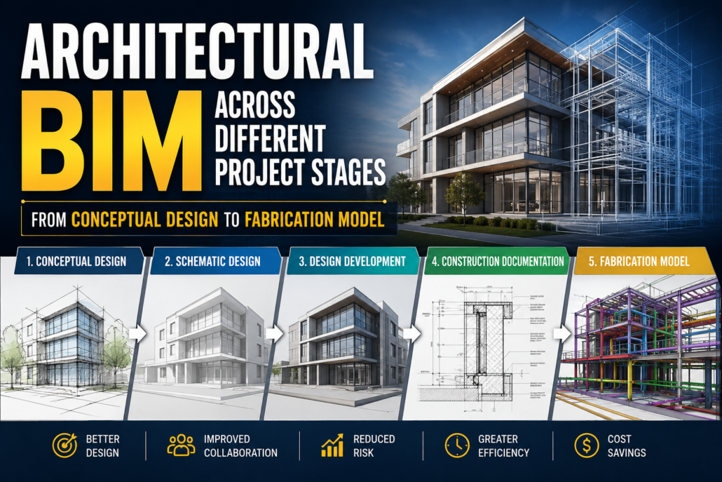
	
Architectural BIM Across Different Project Stages:

Introduction 

Architectural Building Information Modeling (Architectural BIM) has fundamentally transformed the way buildings are designed, coordinated, and constructed. Rather than functioning as a simple three-dimensional drafting tool, Architectural BIM creates an intelligent digital representation of a building that evolves throughout the project lifecycle. Every wall, floor, roof, window, door, and architectural element contains geometric as well as non-geometric information that supports planning, visualization, analysis, coordination, estimation, documentation, and construction. 

One of the greatest strengths of Architectural BIM is that the model develops progressively alongside the design process. During the initial concept stage, the model contains only the information necessary to explore design ideas and building massing. As the project advances, the model gradually incorporates more accurate dimensions, material specifications, construction details, and fabrication information. This gradual refinement ensures that project teams always work with the appropriate level of information for each phase without unnecessarily increasing modeling complexity. The evolution of an architectural BIM model is commonly understood through four major stages: Schematic Design (Conceptual Geometry), Design Development (Approximate Geometry), Construction Documents (Specific Geometry), and Construction Model (Fabrication Model). Each stage serves a unique purpose while contributing to the development of a coordinated and constructible building. 

Schematic Design (Conceptual Geometry) 

The schematic design phase represents the beginning of the architectural design process, where ideas are translated into visual concepts and preliminary building forms. At this stage, the primary objective is not to define construction details but to establish the overall design intent of the project. Architects focus on understanding the client’s requirements, site conditions, functional relationships between spaces, and the general appearance of the proposed building. The BIM model developed during this phase consists of conceptual geometry, which emphasizes simplicity and flexibility rather than precise construction information. 

Conceptual geometry typically includes building masses, preliminary floor layouts, generic walls, roofs, circulation paths, and rough spatial arrangements. These elements are intentionally simplified because the design is expected to undergo multiple revisions before becoming finalized. Instead of concentrating on wall assemblies or window frame profiles, architects use basic shapes to study the building’s proportions, orientation, height, and interaction with the surrounding environment. This allows the design team to evaluate several alternatives quickly without investing time in unnecessary detailing. 

Although the geometry remains simple, the BIM model already contains valuable project information. Room names, approximate floor areas, occupancy estimates, site boundaries, parking layouts, building orientation, and zoning information can all be incorporated into the model. These data enable architects to perform preliminary area calculations, shadow studies, daylight evaluations, and early sustainability analyses. Because BIM provides three-dimensional visualization from the earliest stage, clients and stakeholders can easily understand the proposed design and provide meaningful feedback before significant resources are committed. As a result, schematic design supported by Architectural BIM reduces misunderstandings, encourages collaborative decision-making, and establishes a strong foundation for the remaining stages of the project. 

Design Development (Approximate Geometry) 

After the conceptual design receives approval, the project progresses into the design development phase, where the building begins to take a more realistic and technically coordinated form. During this stage, the Architectural BIM model evolves from simple conceptual masses into approximate geometry, meaning that building components closely resemble their intended construction while still allowing room for refinement. The focus shifts from exploring design ideas to developing coordinated architectural solutions that satisfy functional, structural, and engineering requirements. 

Walls are modeled with realistic thicknesses, doors and windows are placed in their intended locations, staircases and elevator cores are accurately defined, and roof configurations become more detailed. Interior spaces are refined to accommodate furniture layouts, accessibility requirements, circulation patterns, and building services. At the same time, architects begin selecting materials, façade systems, finishes, and structural concepts that align with the project’s aesthetic and performance objectives. 

One of the most valuable aspects of Architectural BIM during design development is multidisciplinary coordination. The architectural model is integrated with structural, mechanical, electrical, plumbing, and fire protection models to identify conflicts before construction begins. Clash detection software helps reveal situations where ducts intersect beams, pipes interfere with walls, or structural columns obstruct architectural spaces. Detecting and resolving these issues digitally saves considerable time and cost compared to making changes during construction. 

The information contained within the BIM model also becomes increasingly comprehensive. Material specifications, wall types, ceiling systems, floor assemblies, door schedules, window schedules, room finishes, and accessibility information are progressively added. These enhancements enable more reliable cost estimation, improved building performance analysis, and better communication among all project participants. Consequently, the design development stage transforms the architectural concept into a coordinated and technically feasible design ready for detailed documentation. 

Construction Documents (Specific Geometry) 

The construction document phase marks the transition from design development to construction preparation. At this point, the architectural design has been thoroughly coordinated and approved, allowing the BIM model to evolve into specific geometry, where every architectural component is represented with precise dimensions, exact locations, and detailed specifications. Unlike previous stages, where certain elements remained approximate, the model now reflects the actual building that contractors will construct. 

Specific geometry includes accurately modeled wall assemblies, slabs, roofs, curtain walls, staircases, windows, doors, ceiling systems, expansion joints, finish layers, and numerous other architectural components. Every element contains sufficient detail to generate reliable construction drawings directly from the BIM model. Floor plans, elevations, sections, reflected ceiling plans, enlarged details, schedules, and material legends are automatically produced while remaining fully coordinated because they all originate from the same centralized digital model. 

Architectural BIM also serves as the primary coordination platform during this phase. Structural framing, HVAC systems, plumbing networks, electrical conduits, fire protection systems, and architectural components are continuously reviewed together to ensure compatibility. Any remaining clashes or inconsistencies are resolved before construction begins, significantly reducing requests for information (RFIs), design revisions, and costly field modifications. 

Beyond geometric accuracy, the model contains extensive non-geometric information such as manufacturer data, fire ratings, acoustic properties, thermal performance values, finish specifications, installation requirements, and product codes. This information supports procurement, specification writing, quantity takeoffs, cost estimation, and regulatory compliance. The result is a highly coordinated documentation package that enables contractors to execute the project with greater confidence, fewer errors, and improved overall efficiency. 

Construction Model (Fabrication Model) 

The final evolution of Architectural BIM is the construction model, commonly referred to as the fabrication model. At this stage, the BIM model extends beyond design documentation and becomes a production-ready digital representation that supports manufacturing, prefabrication, logistics, installation, and field execution. Every architectural component is modeled exactly as it will be fabricated, assembled, transported, and installed on the construction site. 

Fabrication models contain extremely accurate representations of curtain wall panels, precast concrete units, steel connections, glazing systems, modular wall assemblies, architectural metalwork, custom joinery, ceiling suspension systems, and other prefabricated building components. Unlike construction documents, which primarily communicate design intent, fabrication models communicate manufacturing intent. Every dimension, tolerance, connection detail, and assembly sequence is defined with exceptional precision to ensure that fabricated components fit perfectly during installation. 

In addition to geometric accuracy, the model incorporates fabrication-specific information such as assembly numbers, shop drawing references, weld locations, bolt specifications, lifting points, panel identification codes, manufacturing tolerances, and installation sequencing. This information enables manufacturers to automate production using CNC machines and digital fabrication technologies while reducing material waste and minimizing production errors. 

The construction model also plays a central role in modern digital construction workflows. Contractors use it to simulate construction sequencing through 4D scheduling, coordinate material deliveries, optimize crane operations, plan site logistics, and monitor installation progress. Integration with laser scanning, reality capture, drones, augmented reality, and digital twin technologies allows project teams to compare actual site conditions with the BIM model in real time, ensuring that construction remains aligned with design intent. By supporting prefabrication, modular construction, and advanced quality control, fabrication models contribute significantly to shorter project schedules, improved safety, higher construction accuracy, and reduced overall project costs. 

Conclusion 

Stage Geometry Type Primary Purpose Level of Detail 
Schematic Design Conceptual Geometry Design exploration, space planning, client approval Basic massing and conceptual elements 
Design Development Approximate Geometry Design refinement and multidisciplinary coordination Realistic building elements with preliminary specifications 
Construction Documents Specific Geometry Construction documentation and coordinated drawings Precise dimensions, assemblies, schedules, and specifications 
Construction Model Fabrication Model Fabrication, manufacturing, installation, and construction execution Fabrication-ready components with manufacturing and installation data 

Architectural BIM is not a static model but a continuously evolving source of project information that supports every phase of building delivery. Beginning with Schematic Design, where conceptual geometry communicates design intent, the model gradually develops into Design Development, where approximate geometry enables technical coordination. It then progresses to Construction Documents, where specific geometry provides precise construction information, before ultimately reaching the Construction Model, where fabrication-ready data supports manufacturing and on-site installation. 

This progressive development ensures that every stakeholder receives the appropriate level of information at the right time, reducing uncertainty and improving collaboration throughout the project lifecycle. By integrating geometry, data, coordination, and construction intelligence into a single digital environment, Architectural BIM enables architects, engineers, contractors, and owners to make better decisions, minimize errors, enhance efficiency, and deliver higher-quality buildings. As the construction industry continues to embrace digital transformation, understanding the evolution of Architectural BIM across these four stages has become essential for achieving successful, cost-effective, and sustainable project outcomes. 
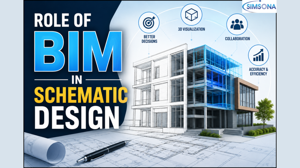
The Role of BIM in Schematic Design || Simsona

BIM SCHEMATIC DESIGN

Introduction

The construction and architecture industries have undergone a major digital transformation over the past two decades, and at the center of this shift lies Building Information Modeling (BIM). Once viewed primarily as a tool for detailed design and documentation, BIM has evolved into a strategic asset that influences every phase of a project lifecycle—especially schematic design.

Schematic design is the stage where ideas begin to take shape. Architects, engineers, and project stakeholders define the project vision, explore alternatives, and establish the building’s overall form, layout, and performance goals. Decisions made during this phase have a lasting impact on project cost, schedule, sustainability, and constructability.

Traditionally, schematic design relied heavily on sketches, 2D drawings, and conceptual models. While these methods encouraged creativity, they often created gaps in coordination, delayed feedback, and limited analytical capabilities. BIM changes this process by introducing intelligent, data-rich digital models that support informed decision-making from the very beginning.

Today, BIM is no longer just a drafting or modeling tool—it is a collaborative design environment that enables teams to visualize, analyze, and refine concepts before construction begins. Its role in schematic design has become increasingly important as projects grow more complex and stakeholder expectations continue to rise.

Understanding BIM and Schematic Design

Before examining BIM’s role, it is useful to understand what schematic design involves.

Schematic design is the early design phase where project goals are translated into preliminary concepts. During this stage, design teams typically focus on:

  • Building massing and form.
  • Spatial organization.
  • Site planning.
  • Preliminary structural and MEP considerations.
  • Design feasibility.
  • Client requirements and project objectives.

The primary goal is not to produce final construction documents but to establish a viable design direction.

BIM enhances this process by creating a digital model that combines geometry with information. Unlike traditional CAD drawings, BIM models contain embedded data related to dimensions, materials, performance, and building systems. This intelligent environment enables designers to evaluate concepts more effectively and collaborate more efficiently.

Improving Concept Development and Design Exploration

One of BIM’s most valuable contributions to schematic design is its ability to support rapid concept development.

Architects often explore multiple design alternatives before selecting a preferred solution. Traditional workflows may require redrawing plans or manually coordinating revisions, which consumes time and increases the risk of inconsistencies.

BIM simplifies this process by allowing designers to create and modify conceptual models dynamically. Changes made to one part of the model automatically update related views, sections, and schedules. This parametric capability enables teams to test different layouts, massing strategies, and design ideas without starting from scratch.

As a result, design exploration becomes faster and more flexible.

Instead of spending excessive time managing drawings, teams can focus on evaluating design quality and project outcomes. This supports a more iterative and creative design process where informed experimentation is encouraged.

For example, an architect designing a commercial office building can quickly compare several façade options or floor arrangements while maintaining coordination across the model.

Enhanced Visualization and Client Communication

Communicating design intent is often one of the biggest challenges during schematic design.

Clients and non-technical stakeholders may struggle to interpret 2D drawings and technical plans. Misunderstandings at this stage can lead to design revisions, delays, and dissatisfaction later in the project.

BIM significantly improves communication through advanced visualization.

Three-dimensional models provide a realistic representation of the proposed design, helping stakeholders understand:

  • Building scale.
  • Interior and exterior spaces.
  • Material relationships.
  • Site integration.
  • User experience.

These visual models make design discussions more productive and transparent.

Instead of relying solely on abstract plans, project teams can conduct walkthroughs and present realistic perspectives that illustrate how the building will function and appear.

This capability strengthens client confidence and encourages earlier decision-making.

For developers and project owners, BIM visualization also supports marketing and stakeholder approvals by presenting concepts in a compelling and accessible format.

Strengthening Collaboration Across Disciplines

Schematic design involves input from multiple disciplines, including architecture, structural engineering, mechanical systems, and construction planning.

In traditional workflows, coordination often occurs through separate drawings and isolated communication channels. This fragmented approach can create information silos and lead to conflicting design decisions.

BIM addresses this challenge by creating a shared digital environment.

All project participants work with coordinated information, improving transparency and reducing misunderstandings. Rather than exchanging disconnected files, teams collaborate around a common model.

This collaborative approach offers several advantages:

  • Faster coordination.
  • Improved information accuracy.
  • Reduced duplication of work.
  • Better alignment of project goals.

Early interdisciplinary collaboration is particularly valuable because many project conflicts originate during conceptual planning.

For instance, a structural engineer may identify issues with column placement that affect architectural layouts, or an MEP consultant may suggest system routing considerations that influence ceiling heights. BIM allows these conversations to occur early, when design modifications are easier and less costly.

The result is a more integrated and coordinated design process.

Early Cost Estimation and Budget Control

Cost certainty is a major concern during schematic design.

Project owners need early insight into budget implications before committing to design decisions. However, traditional conceptual estimating often relies on rough assumptions and limited information.

BIM improves cost forecasting by linking design geometry with quantifiable data.

As the schematic model develops, teams can generate preliminary quantity takeoffs and material estimates directly from the model. This creates a stronger connection between design decisions and financial impact.

Early cost analysis enables stakeholders to:

  • Compare design alternatives.
  • Evaluate value-engineering opportunities.
  • Maintain budget alignment.
  • Reduce financial uncertainty.

For example, modifying floor area, façade systems, or structural configurations can immediately influence quantity estimates and associated costs.

This real-time feedback helps prevent situations where attractive design concepts later prove financially unrealistic.

By integrating cost awareness into schematic design, BIM supports better financial decision-making and minimizes redesign caused by budget overruns.

Supporting Design Analysis and Building Performance

Modern projects are expected to meet increasingly demanding performance standards.

Energy efficiency, occupant comfort, daylight access, and environmental impact are no longer secondary considerations—they are central design priorities.

BIM allows performance analysis to begin during schematic design rather than after major decisions have already been made.

Using BIM-based analytical tools, designers can assess:

  • Solar exposure.
  • Daylighting conditions.
  • Energy performance.
  • Ventilation strategies.
  • Building orientation.
  • Thermal behavior.

This early analysis enables teams to optimize building performance before designs become fixed.

For example, adjusting building orientation or window placement during schematic design can significantly improve energy efficiency and reduce operational costs.

Traditional methods often delayed these evaluations until later project stages, limiting opportunities for meaningful change.

BIM supports a more proactive design approach where performance considerations are embedded into conceptual development.

Reducing Design Risks Through Early Clash Detection

Clash detection is commonly associated with detailed coordination, but BIM’s benefits begin much earlier.

During schematic design, preliminary coordination models can reveal conflicts between architectural, structural, and building systems.

These may include:

  • Spatial conflicts.
  • Structural alignment problems.
  • Mechanical routing limitations.
  • Inadequate service zones.

Identifying such issues early reduces downstream design complications.

Traditional coordination methods frequently discovered conflicts during construction documentation or even during construction itself—when corrections became expensive and disruptive.

BIM enables teams to anticipate problems while design flexibility remains high.

Early clash awareness reduces project risk and contributes to smoother project delivery.

This preventive approach is especially valuable for complex facilities such as hospitals, airports, and mixed-use developments where system integration is highly demanding.

Encouraging Sustainable and Resilient Design

Sustainability is increasingly influencing design decisions across the built environment.

Regulatory requirements, environmental goals, and client expectations are pushing project teams to prioritize sustainable design strategies from the earliest stages.

BIM plays a significant role in this shift.

Because BIM models contain both geometry and performance-related information, they support sustainability analysis during schematic design.

Design teams can evaluate:

  • Carbon impact.
  • Material efficiency.
  • Water usage strategies.
  • Energy demand.
  • Passive design opportunities.

This capability allows sustainability to become an active design driver rather than a late-stage compliance exercise.

BIM also contributes to long-term resilience planning by supporting informed decisions about building systems, operational efficiency, and lifecycle performance.

As climate-responsive design becomes increasingly important, BIM provides a practical framework for achieving sustainability objectives.

Challenges and Limitations of BIM in Schematic Design

Despite its advantages, BIM implementation during schematic design is not without challenges.

One common concern is the perception that BIM may constrain creativity.

Some designers worry that digital modeling encourages premature technical detail or limits conceptual freedom. However, this largely depends on workflow and software use. BIM should support creative exploration rather than replace it.

Another challenge involves investment and training.

Effective BIM adoption requires:

  • Skilled personnel
  • Software resources
  • Process standardization
  • Organizational commitment

Smaller firms may face barriers related to cost and expertise.

Interoperability can also create difficulties when different consultants use incompatible software platforms or data standards.

Additionally, developing BIM models too early or at excessive detail can reduce efficiency and create unnecessary workload.

Successful implementation therefore requires balanced modeling strategies aligned with project objectives.

The Future of BIM in Schematic Design

The role of BIM in schematic design continues to expand.

Emerging technologies are making BIM environments more intelligent and data-driven.

Several trends are shaping the future:

Generative Design
Algorithms can produce multiple design options based on defined goals such as area efficiency, daylight performance, or cost targets.

Artificial Intelligence
AI-assisted workflows can evaluate design alternatives and provide predictive insights that support decision-making.

Cloud Collaboration
Cloud-based BIM platforms enable distributed teams to collaborate in real time, improving communication and project accessibility.

Digital Twins
BIM models are increasingly evolving into digital twins that connect design data with operational performance throughout the building lifecycle.

These developments suggest that BIM will play an even greater strategic role during conceptual planning and early decision-making.

Rather than simply documenting design ideas, BIM is becoming a platform for generating, evaluating, and optimizing them.

Conclusion

Schematic design is where critical project decisions are made, and BIM has fundamentally transformed how those decisions are developed and evaluated.

By improving visualization, strengthening collaboration, enabling early cost and performance analysis, and reducing coordination risks, BIM creates a more informed and efficient design environment. It allows project teams to move beyond static drawings toward integrated, data-rich workflows that support better outcomes.

While challenges related to adoption, training, and process management remain, the benefits of BIM during schematic design are increasingly difficult to ignore.

As technology continues to evolve, BIM is poised to become not merely a design tool but a central decision-making framework for the future of architecture and construction. Firms that embrace BIM early in schematic design are better positioned to deliver projects that are innovative, coordinated, sustainable, and aligned with client expectations.