
How BIM Reduces Rework in Steel Fabrication
Introduction
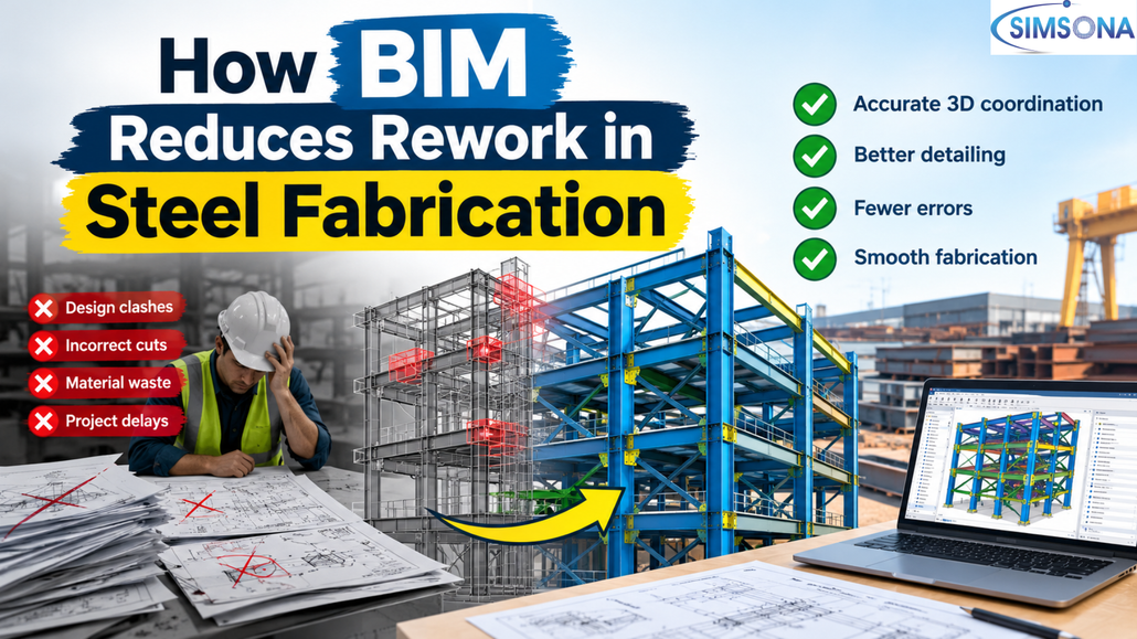
Steel fabrication requires accuracy at every stage, from interpreting structural design drawings to preparing shop drawings, cutting steel members, drilling bolt holes, welding connections, and assembling components. Even a small mistake in dimensions, connection details, or material specifications can create problems during fabrication or on the construction site. When these errors are discovered late, fabricators may need to modify components, replace materials, repeat welding operations, or delay deliveries.
Building Information Modeling (BIM) helps reduce rework in steel fabrication by identifying design conflicts early, improving detailing accuracy, coordinating different building systems, and maintaining consistency between the structural design and fabrication drawings. Instead of relying entirely on separate drawings and manual checks, project teams can use a coordinated 3D model to review how steel components fit together before manufacturing begins.
For steel fabricators, structural engineers, general contractors, and steel detailing companies, BIM provides a more reliable way to manage complex projects, reduce avoidable errors, and improve fabrication efficiency.
Understanding Rework in Steel Fabrication
Rework occurs when a fabricated steel component, drawing, or assembly must be corrected because it does not meet the project’s design requirements, dimensions, specifications, or installation conditions. These problems can originate during structural design, steel detailing, fabrication, transportation, or erection.
For example, a beam may be fabricated with an incorrect length, a column may have an improperly positioned connection plate, or bolt holes may not align with the corresponding holes in another member. In other situations, a steel connection may conflict with an HVAC duct, pipe, or cable tray that was not adequately coordinated during the design stage.
Such issues can require additional cutting, drilling, welding, material replacement, engineering reviews, and site adjustments. They also consume labour and equipment time that could otherwise be used for productive work.
The challenge is that many fabrication errors are not immediately visible in two dimensional drawings. A connection may look correct in an individual shop drawing but fail to fit properly when assembled with surrounding members. BIM helps address this problem by allowing teams to examine the relationships between components in a coordinated three dimensional environment.
How BIM Reduces Rework in Steel Fabrication
1. Identifying Design Errors Before Fabrication Begins
One of the most important advantages of BIM is the ability to identify design inconsistencies before steel components enter the fabrication process. Traditional workflows often depend on reviewing structural drawings, architectural drawings, and connection details separately. Although these drawings contain important information, interpreting how every component interacts can be difficult, especially in complex industrial buildings, commercial structures, and large infrastructure projects.
With BIM, steel members can be represented in a coordinated 3D model containing information about their geometry, dimensions, positions, and connections. Detailers and engineers can inspect beam to column connections, bracing arrangements, base plates, stiffeners, and other structural elements before fabrication drawings are finalized.
For example, if a brace intersects a beam connection in a way that prevents the intended assembly, the team can identify the problem during model review. The connection can then be revised and checked before cutting or welding begins.
Early identification reduces the likelihood of discovering design problems after materials have been processed. It also gives engineers and detailers more time to evaluate solutions without the pressure of correcting an error on the shop floor or at the construction site.
2. Improving Steel Detailing Accuracy
Steel detailing translates structural engineering design into the detailed information required to manufacture and assemble steel components. This includes member dimensions, connection geometry, bolt arrangements, weld specifications, hole locations, material grades, and assembly information.
Errors in steel detailing can directly lead to fabrication rework. An incorrect beam length, misplaced hole, missing stiffener, or inconsistent connection detail may require a component to be modified or manufactured again.
BIM based steel detailing software, such as Tekla Structures, allows detailers to develop a coordinated model of structural steelwork and generate fabrication information from that model. Rather than treating every drawing as an independent source of geometry, the team can maintain a common model from which relevant views, dimensions, and details are produced.
When a beam length or connection geometry changes, the associated model views and drawings can be updated through the software’s supported workflows. This helps reduce discrepancies between the 3D model and the corresponding fabrication documentation.
However, accurate output still depends on correct modelling, appropriate software settings, engineering approval, and quality checks. BIM does not automatically guarantee that every connection or dimension is correct. Its value lies in providing a more coordinated environment for creating, reviewing, and communicating accurate detailing information.
3. Detecting Clashes Between Steel and Other Building Systems
A steel structure does not exist in isolation. It must accommodate architectural elements, mechanical systems, electrical services, plumbing, fire protection, and other building components. If these systems are designed or coordinated independently, conflicts can remain hidden until fabrication or installation.
For instance, a large HVAC duct may occupy the same space as a steel beam. A pipe may interfere with a bracing member, or a cable tray may pass through an area where a connection plate or stiffener is required.
Correcting these conflicts after steel fabrication can be expensive because structural members may already have been cut, drilled, welded, painted, or transported to the site.
BIM based coordination helps teams compare the structural steel model with architectural and MEP models. Clash detection tools can identify overlapping or spatially conflicting components so that the responsible teams can review the issue and agree on a suitable resolution.
The team may need to reroute a duct, adjust a service layout, revise a connection, or obtain an engineering approved change to the structural arrangement. The correct solution depends on the design requirements and the nature of the conflict.
By resolving these issues before fabrication, BIM reduces the risk of site modifications, unnecessary cutting, and delays caused by coordination failures.
4. Ensuring Consistency Between Shop Drawings and the 3D Model
Shop drawings are essential for communicating how individual steel members and assemblies must be fabricated. They provide the dimensions, connection details, material information, and other instructions needed by fabrication teams.
When drawings are produced or revised separately from the underlying design information, inconsistencies can develop. A connection might be updated in one drawing but remain unchanged in another. Fabricators may then work from outdated information, resulting in components that no longer match the approved design.
A model based BIM workflow helps reduce this risk by linking fabrication documentation to the coordinated steel model. Detailers can generate general arrangement drawings, assembly drawings, single part drawings, and other required outputs using information maintained within the model.
When revisions occur, the team can identify affected components and update the relevant documentation through the appropriate revision process. Revision tracking and controlled drawing distribution remain important because previously issued documents do not necessarily update automatically in the hands of every project participant.
For steel fabricators, this coordination helps ensure that the shop floor receives the correct, approved information before manufacturing begins.
5. Reducing Material Waste and Incorrect Cutting
Steel fabrication involves processing raw material into beams, columns, plates, angles, channels, and other components. Incorrect dimensions, incomplete material information, or outdated revisions can result in unnecessary material waste.
For example, if a beam is cut to the wrong length, the component may be unusable for its intended assembly. Depending on the design and material requirements, the fabricator may need to replace the member or seek an approved repair solution.
BIM supports material accuracy by maintaining component dimensions and quantities within a coordinated model. When combined with appropriate detailing and fabrication software, the model can help generate material lists, cutting information, bolt lists, and other production data.
These outputs allow fabricators to compare required materials with procurement and production information before processing begins. They can also support material planning and cutting optimization, depending on the capabilities of the connected software and the quality of the model data.
The benefit is not limited to reducing scrap. Correct material information also helps prevent unnecessary procurement, avoid duplicate processing, and improve the coordination of fabrication activities.
6. Improving Connection Design and Assembly Fit
Steel connections require particular attention because they determine how individual members fit together and transfer loads through the structure. Beam to column connections, moment connections, bracing connections, splice connections, and base plates must follow the approved engineering design and applicable project requirements.
If connection geometry is incorrect, bolt holes may not align, plates may interfere with adjacent members, or weld access may be restricted. These problems can create difficulties during fabrication and erection.
A detailed BIM model allows teams to inspect connections in three dimensions and identify geometric problems before components are manufactured. Detailers can examine plate positions, bolt groups, stiffeners, clearances, and the relationship between connected members.
Where appropriate, connection design and verification tools can support checks against specified engineering requirements. However, visual inspection alone cannot confirm structural adequacy. Connection capacities, weld sizes, bolt specifications, and other engineering requirements must be checked using approved calculations, design methods, and project standards.
By combining model based coordination with engineering review, project teams can reduce avoidable fit up problems and improve the likelihood that steel assemblies will match the approved design during erection.
7. Managing Design Changes Without Creating More Errors
Design changes are common in construction projects. A structural engineer may revise a beam size, an architect may adjust a building layout, or an MEP designer may change a service route. Even a small revision can affect several connected steel members and their fabrication drawings.
When changes are communicated through disconnected drawings, emails, and spreadsheets, there is a risk that some team members will continue using superseded information.
BIM provides a coordinated environment in which revisions can be reviewed against the model and their effects on connected components can be assessed. The team can identify affected members, review connection implications, and determine which drawings, material lists, or fabrication instructions require revision.
For example, increasing the depth of a beam may affect a nearby duct, the geometry of a beam to column connection, and the clearance available for another structural member. Reviewing these relationships before releasing revised fabrication information helps prevent errors from spreading across the project.
Effective revision management also requires clear approval procedures, revision identifiers, issue registers, and communication between engineering, detailing, procurement, and fabrication teams. BIM supports this process, but disciplined document control is necessary to make it effective.
8. Improving Coordination Between Detailers, Engineers, and Fabricators
Rework can arise not only from technical errors but also from communication gaps. Structural engineers, steel detailers, fabrication managers, site engineers, and contractors may interpret the same design requirement differently if information is incomplete or unclear.
BIM improves communication by giving project participants a shared visual reference for reviewing the steel structure. Instead of discussing a complicated connection using several drawing references, the team can examine the relevant area of the model and understand the position of each component.
This is particularly useful when reviewing unusual connections, congested structural zones, erection constraints, or conflicts between steelwork and building services.
Model based reviews can also help teams identify missing information before fabrication. If a connection requires clarification or a structural detail is incomplete, the issue can be raised through the project’s established review and RFI process rather than being left for the fabrication team to resolve independently.
Better coordination reduces misunderstandings, limits avoidable revisions, and helps ensure that fabrication decisions are based on approved information.
The Role of BIM in the Steel Fabrication Workflow
BIM delivers the greatest benefit when it is integrated into the entire steel detailing and fabrication workflow rather than used only to create a 3D visualization.
The process typically begins with structural design information, which is interpreted and developed into a detailed steel model. Detailers then review member geometry, connection arrangements, clearances, and constructability. Coordination checks are carried out against other building systems, and identified issues are resolved with the relevant design teams.
Once the model and associated information have passed the required checks and approvals, the detailing team prepares fabrication drawings, material lists, and production information. Fabricators use the approved deliverables to plan cutting, drilling, welding, assembly, and other manufacturing operations.
During production, revisions must be controlled so that the shop floor does not use outdated information. During erection, feedback from the site can be communicated to the project team and incorporated into the appropriate model and documentation updates.
This workflow establishes a connection between design intent, detailed modelling, fabrication requirements, and site installation. Each stage provides an opportunity to identify and correct errors before they create more expensive problems downstream.
BIM vs Traditional Steel Fabrication: How Rework Risks Differ
| Area | Traditional drawing based workflow | BIM based workflow |
|---|---|---|
| Design coordination | Relies heavily on drawing reviews and manual comparison | Supports coordinated model reviews across disciplines |
| Steel detailing | Dimensions and details may be maintained across separate documents | Model based detailing can improve consistency between components and drawings |
| Clash detection | Conflicts may be discovered during manual checks or installation | Automated and visual clash checks can identify many conflicts earlier |
| Design revisions | Changes may need to be tracked across multiple documents | Model based reviews help identify affected components and outputs |
| Material planning | Depends on the accuracy and coordination of schedules and takeoffs | Model derived quantities can support material lists and planning |
| Connection review | Often relies on individual details and drawing interpretation | Three dimensional inspection improves visibility of connection geometry |
| Fabrication readiness | Errors may remain hidden until components are processed | Pre-fabrication model reviews provide additional quality control opportunities |
Traditional workflows can still achieve excellent results when drawings, coordination procedures, and quality checks are well managed. BIM is not a substitute for engineering expertise or fabrication quality control. Its main advantage is the ability to make relationships between components easier to inspect and maintain across the project.
How BIM Helps Reduce Fabrication Costs and Project Delays
The financial impact of rework extends beyond the cost of replacing an incorrect steel component. A single fabrication error can require additional labour, machine time, consumables, engineering reviews, transportation, and site coordination.
If a replacement component is needed, the fabrication sequence may have to be rearranged. Other trades may be unable to continue their work until the affected steel member is corrected or installed. Delayed deliveries can also disrupt erection schedules and equipment planning.
BIM helps reduce these risks by moving more error detection and coordination activities to the design and detailing stages. When a problem is discovered in the model, the team can often review potential solutions before committing materials and production resources.
The exact savings depend on project complexity, the quality of the existing workflow, the level of BIM implementation, and how effectively identified issues are resolved. BIM should therefore be viewed as a method for reducing avoidable rework risk rather than a guarantee that fabrication errors or delays will disappear.
Fabricators can evaluate its effectiveness by tracking indicators such as drawing revisions caused by errors, rejected components, nonconformance reports, material scrap, site modifications, and hours spent on rework.
Best Practices for Using BIM to Prevent Steel Fabrication Rework
To obtain consistent results, steel fabrication teams should establish clear modelling and quality control procedures before the detailing process begins.
First, define the project’s modelling requirements, including levels of detail, naming conventions, connection information, coordinate systems, and deliverable formats. Clear requirements help ensure that the model contains the information needed for coordination and fabrication.
Second, establish a structured review process for geometry, connections, clearances, and clashes. Automated checks should be supplemented by engineering review and manual inspection wherever necessary.
Third, maintain a controlled revision process. Every change that affects fabrication should be reviewed, approved by the responsible parties, and communicated to the relevant production teams. Superseded drawings and model information should be clearly identified.
Fourth, validate material lists and fabrication outputs before they are released. Quantities, member marks, dimensions, material grades, bolt specifications, and other critical information should be checked against the approved design and project requirements.
Finally, collect feedback from fabrication and erection teams. Recurring problems can reveal weaknesses in modelling practices, connection detailing, coordination procedures, or document control. Using this information to improve future projects helps establish a continuous quality improvement process.
Conclusion
BIM reduces rework in steel fabrication by improving coordination, strengthening detailing accuracy, identifying clashes, supporting material planning, and helping project teams manage design revisions. Its greatest value comes from detecting problems before they reach the fabrication shop or construction site, where corrections generally involve more resources and greater disruption.
For steel fabricators and detailing companies, a coordinated BIM workflow connects the structural model with shop drawings, material information, and fabrication requirements. When supported by accurate modelling, engineering verification, revision control, and systematic quality checks, this approach can improve fabrication readiness and reduce avoidable errors.
For companies handling complex steel structures, adopting BIM is not simply about creating a three dimensional model. It is about building a more coordinated and reliable process in which design, detailing, fabrication, and erection teams work from consistent, approved information.
Frequently Asked Questions
1. How does BIM reduce rework in steel fabrication?
BIM helps reduce rework by identifying design errors, detecting clashes, improving steel detailing accuracy, coordinating shop drawings, and managing design revisions before fabrication begins.
2. Can BIM prevent steel fabrication errors completely?
No. BIM can identify many geometric, coordination, and documentation problems, but errors can still occur because of incorrect modelling, unsuitable assumptions, engineering mistakes, or production issues. Independent checks and quality control remain essential.
3. How does clash detection help steel fabricators?
Clash detection identifies spatial conflicts between steel members and other building systems, such as HVAC ducts, pipes, and cable trays. Resolving these conflicts before fabrication reduces the likelihood of cutting, modifying, or replacing components later.
4. Which BIM software is used for steel fabrication?
Software such as Tekla Structures is widely used for steel detailing and fabrication workflows. Autodesk Revit, Navisworks, and other coordination tools may also be used, depending on project requirements and the software ecosystem.
5. How does BIM improve steel shop drawings?
BIM based detailing allows shop drawings to be generated from a coordinated model, helping maintain consistency in dimensions, member information, and connection details. Drawing revisions must still be checked, approved, and distributed through a controlled process.
6. Does BIM reduce material waste in steel fabrication?
BIM can help reduce material waste by improving dimensional accuracy, supporting quantity takeoffs, and reducing the risk of fabricating components from incorrect or outdated information. Cutting optimization and material verification may require additional fabrication software and procedures.
7. Is BIM useful for small steel fabrication projects?
Yes. The level of implementation should match the project’s size and complexity. Even a relatively small project can benefit from coordinated 3D detailing, connection reviews, and accurate fabrication documentation when the cost of errors would be significant.

 301-774-0880